Modular fuel injector with a harmonic damper and method of reducing noise

Inactive Publication Date: 2005-12-08
CHO YONG D
View PDF15 Cites 25 Cited by
  • Summary
  • Abstract
  • Description
  • Claims
  • Application Information

AI Technical Summary

Benefits of technology

[0006] In yet another aspect, the present invention provides for a method of maintaining operational noise of a fuel injector at a predetermined noise level. The fuel injector has a body extending along a longitudinal axis and a valve group subassembly. The valve group subassembly includes an inlet tube having a portion disposed withi

Problems solved by technology

In one example, annular dampening elements also have been included as part of the fuel injector nozzle body, but at the f

Method used


Image

  • Modular fuel injector with a harmonic damper and method of reducing noise
  • Modular fuel injector with a harmonic damper and method of reducing noise
  • Modular fuel injector with a harmonic damper and method of reducing noise

Examples


Embodiment Construction

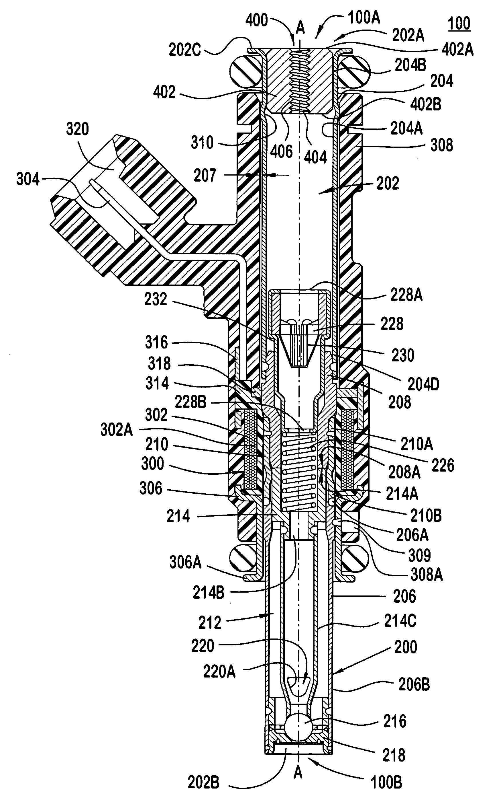
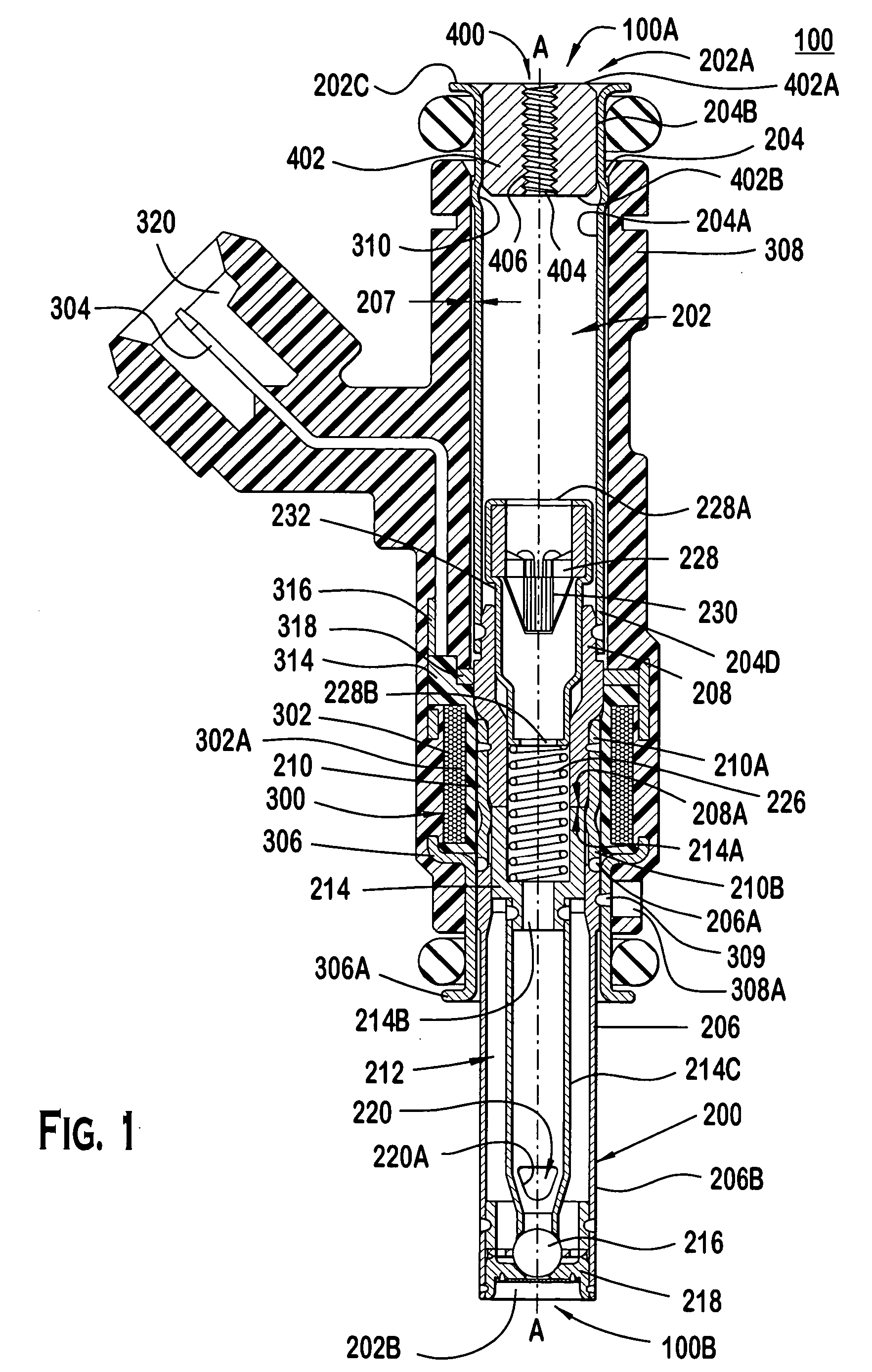
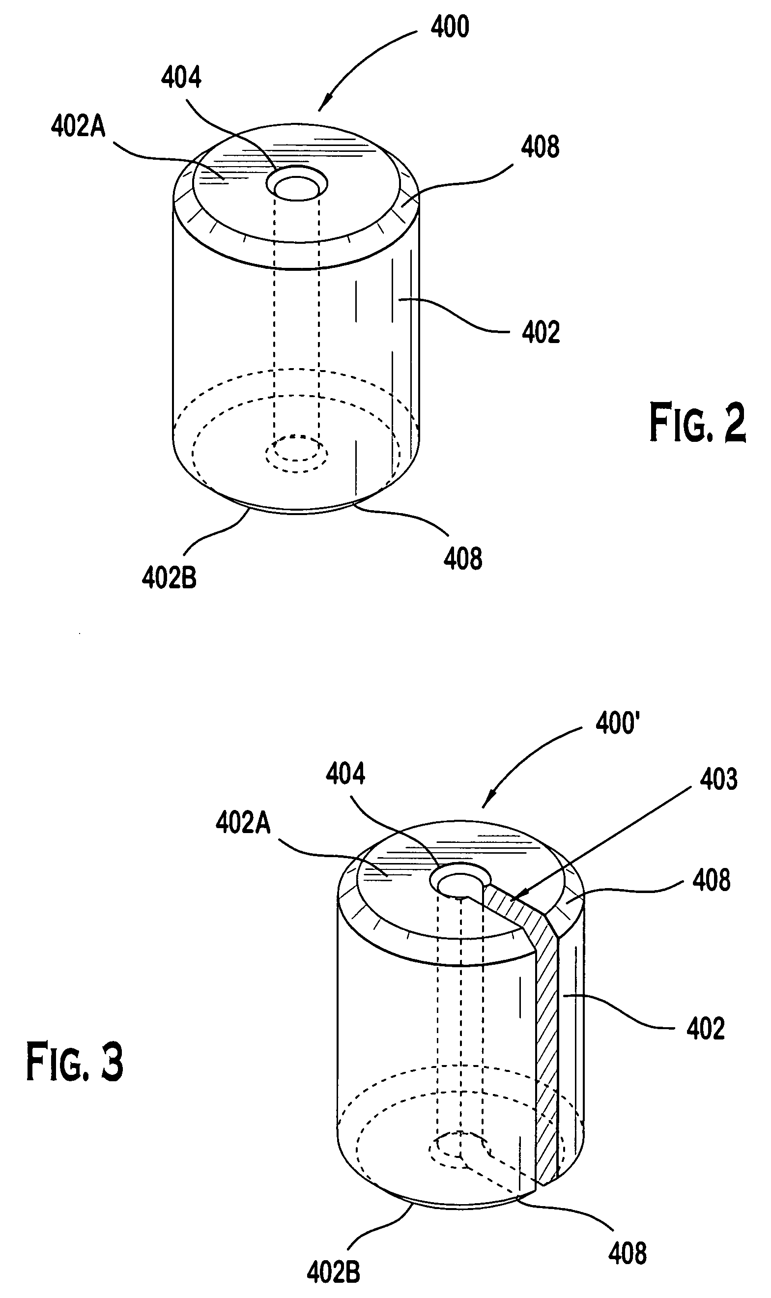
[0011]FIGS. 1-3 illustrate preferred embodiments. Referring to FIG. 1, a solenoid actuated fuel injector 100 dispenses a quantity of fuel to be combusted in an internal combustion engine (not shown). The fuel injector 100 extends along a longitudinal axis A-A between a first injector end 100A and a second injector end 100B, and includes a valve group subassembly 200, a power group subassembly 300 and a harmonic damper 400. The valve group subassembly 200 performs fluid-handling functions, e.g., defining a fuel flow path and prohibiting fuel flow through the injector 100 when a closure member 216 is not actuated. The power group subassembly 300 performs electrical functions, e.g., converting electrical signals to a driving force for permitting fuel flow through the injector 100. The harmonic damper 400 performs a noise reduction function, e.g., attenuating vibrations being transmitted through the fuel injector and therefore reduces acoustic noise emanating from the fuel injector.

[00...


PUM


Abstract

A fuel injector with various embodiments of a damper that reduces noise generated between a valve group subassembly and a power group subassembly during operation of the fuel injector. A mass damper is also shown and described. A method of reducing sound in the valve group subassembly is also disclosed.

Description

BACKGROUND OF THE INVENTION [0001] It is believed that some fuel injectors include features that reduce undesirable noise associated with operation of the fuel injector. For example, it has been known to locate a silencing chamber around the outlet end of the fuel injector. But this is believed to address noise caused by the expansion of gaseous fuel, not noise propagated by the actuator. [0002] It is also known to provide a noise insulator formed in or around the fuel injector to prevent transmission of noise from the fuel injector. In one example, annular dampening elements also have been included as part of the fuel injector nozzle body, but at the fuel-metering section of the armature such that it is believed to be difficult to install, particularly post-manufacturing. [0003] Another known example provides for a sound-dampening element formed unitarily as part of a fuel filter. The sound-dampening element, however, is believed to absorb noise propagating between the fuel injecto...

Claims


Application Information

Patent Timeline
IPC IPC(8): B05B1/30F02M47/02F02M51/06F02M59/00F02M61/00F02M61/04F02M61/16F02M63/00F02M65/00
CPCF02M51/0682F02M61/042F02M61/166F02M61/168F02M2200/9076F02M2200/09F02M2200/315F02M2200/8061F02M2200/9053F02M65/00
Inventor CHO, YONG D.
Owner CHO YONG D
Why Eureka
Try Eureka