
Ball joint for steering knuckle

a ball joint and steering knuckle technology, applied in the direction of suspensions, vehicle components, pivoted suspension arms, etc., can solve the problems of a limited ability to lower the vehicle, the late model truck cannot be lowered by traditional drop spindles, and the shortened service life of the vehicle, so as to reduce the ride height of the vehicle and save costs

Active Publication Date: 2009-06-23
KW AUTOMOTIVE NORTH AMERICA
View PDF18 Cites 6 Cited by
  • Summary
  • Abstract
  • Description
  • Claims
  • Application Information

AI Technical Summary

Benefits of technology

"The present invention is a modified ball joint assembly for attachment to a steering knuckle and lower control arm of a vehicle. The assembly allows for a lower vehicle chassis without the need for replacing the steering knuckle or wheel rims. The assembly includes a body with a ball joint at one end and a set of attachment openings at the other end. A spacer inserts into a void in the lower control arm and includes complementary attachment openings for attaching the body and lower control arm. The assembly also includes an adaptor that extends the connection between the ball joint and the lower control arm, providing a significant offset distance between the two. The assembly is simple to install and allows for the use of the original steering knuckle and wheels. The invention provides an alternative to replacing the steering knuckle with a drop spindle and allows for aftermarket vehicle lowering without the need for significant modifications to the vehicle."

Problems solved by technology

These differences in the design of these recent factory steering knuckles have taken away virtually all of the space previously available to accomplish the vehicle lowering function using existing drop spindle designs.
Accordingly, late model trucks are unable to be lowered by traditional drop spindles.
As stated above, this, like other drop spindles on live axles succumbs to the problem of a limited capability to lower the vehicle.
In addition, the disassembly, removal and replacement of the steering knuckle of the vehicle are burdensome.

Method used


Image

  • Ball joint for steering knuckle
  • Ball joint for steering knuckle
  • Ball joint for steering knuckle

Examples


Embodiment Construction

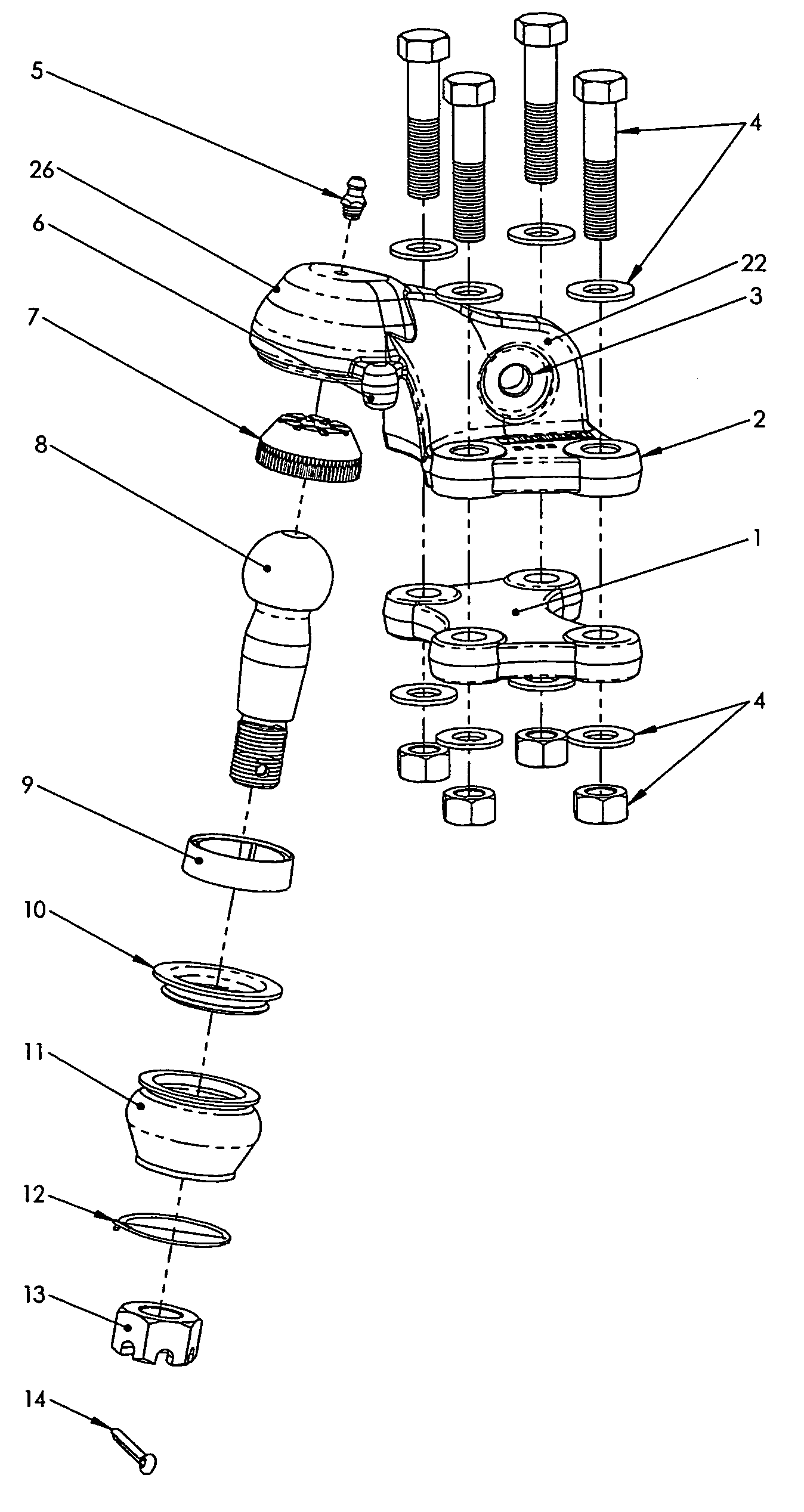
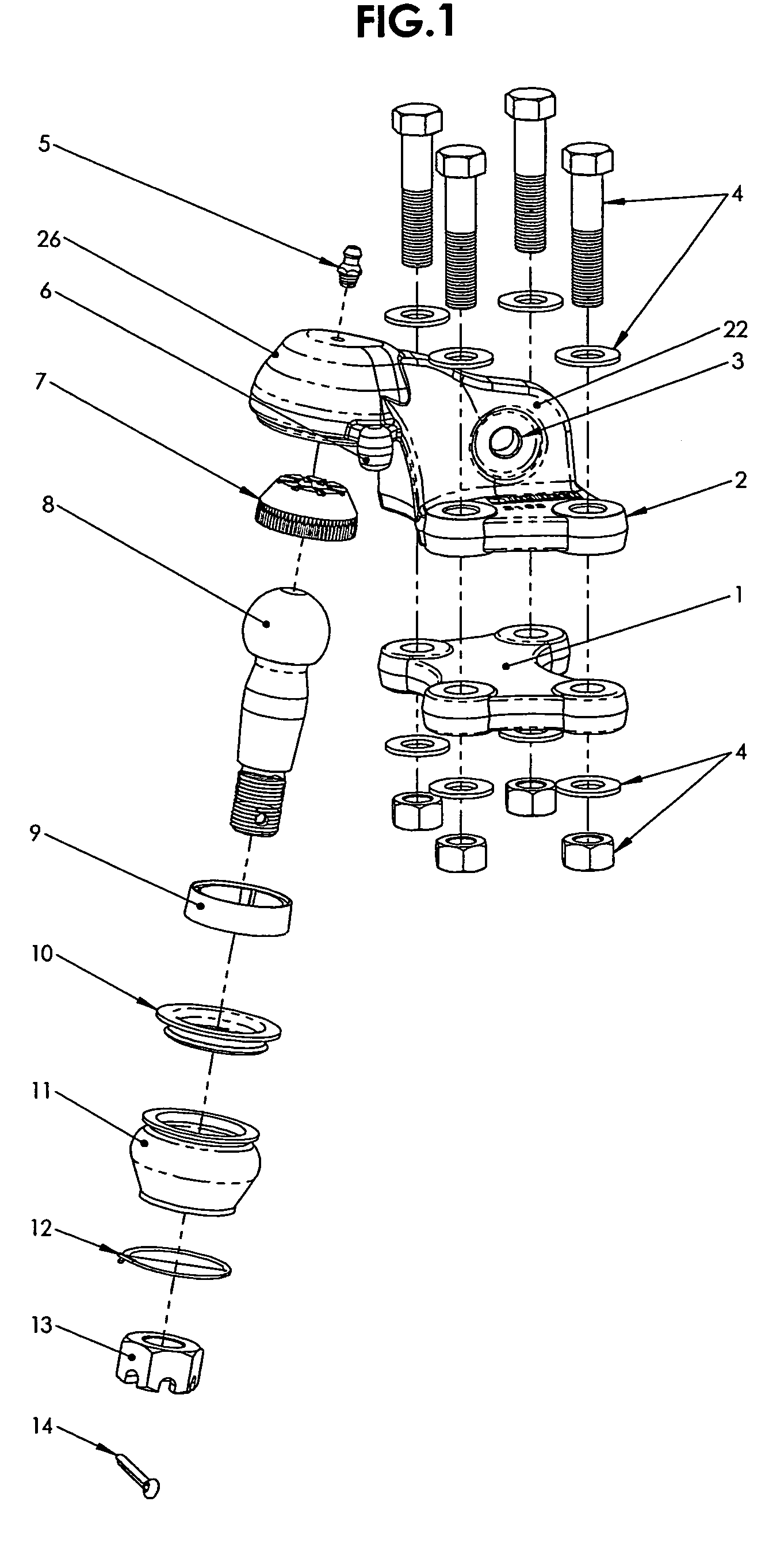
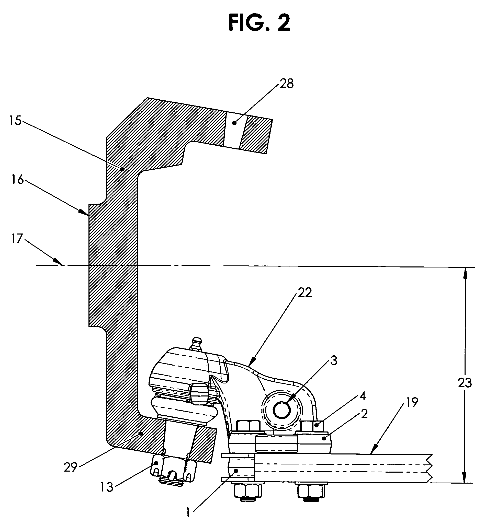
[0030]Referring to the drawings wherein like reference characters designate like or corresponding parts throughout the several views, and referring particularly to FIGS. 1 and 2, it is seen that a typical offset ball joint of the present invention includes a sub-plate or spacer 1 which is inserted into a void the lower control arm 19 of the vehicle created by the removal of the factory ball joint 18. The spacer 1 increases the stability of the control arm 19 and prevents compression of the control arm by the fasteners 4. The lower portion 2 of the offset ball joint of the present invention is attached to the spacer 1 for firm attachment to the lower control arm. Both lower portion 2 and spacer 1 include a plurality of corresponding bolt holes for use in attachment to the lower control arm 19. A plurality of fasteners 4, such as a combination of bolts, washers, and / or nuts are used to securely fasten the lower portion 2, control arm 19, and spacer 1.

[0031]The main body 22 of the pres...


PUM


Abstract

The present invention is a modified ball joint assembly for attachment to a steering knuckle made up of a body and a spacer. The body includes a ball joint at one end, a set of attachment openings at the other end, and a variably spaced segment between the ends. The spacer inserts into a void in the lower control arm of the vehicle, and includes a plurality of complementary attachment openings for use in attaching the body and the spacer to the lower control arm. The modified ball joint assembly lowers the position of the lower control arm of the vehicle relative to the steering knuckle thereby lowering the ride height of a vehicle a desired amount without requiring the removal of or modification of the steering knuckle. The present invention allows the factory-supplied steering knuckle and tires to be used, providing a considerable cost savings to the end user. The ball joint assembly of the present invention may be used to lower the vehicle chassis on vehicles where the steering knuckles is of the large-bore “live” wheel hubs, including four-wheel drive trucks.

Description

[0001]This application claims the benefit of U.S. Provisional Application No. 60 / 567,034, filed on Apr. 30, 2004, which is incorporated herein by this reference.BACKGROUND OF THE INVENTION[0002]1. Field of the Invention[0003]The present invention relates to steering knuckles, and more particularly to a unique ball joint for use on a steering knuckle that lowers the height of a vehicle (i.e., a drop spindle ball joint).[0004]2. Description of the Prior Art[0005]It has become popular to customize vehicles by lowering the height of such vehicles relative to the ground. Lowering vehicles usually improves ride handling and is also done for aesthetic purposes, especially in light trucks. At the front end of the vehicle, lowering has been accomplished by replacing the factory-made (stock) steering knuckle provided with the new vehicle with an alternative after-market steering knuckle that lowers the vehicle height. Such vehicle-lowering steering knuckles are commonly referred to as “drop s...

Claims


Application Information

Patent Timeline
Patent Type & Authority Patents(United States)
IPC IPC(8): B62D7/16B60G7/00B62D7/20
CPCB60G7/008B62D7/166B60G2204/416B60G2204/1224B60G2206/8207
Inventor BIER, MATTHEW
Owner KW AUTOMOTIVE NORTH AMERICA
Learn More