Nail holding and driving device

a technology of driving device and nail, which is applied in the direction of nailing tools, stapling tools, manufacturing tools, etc., can solve the problems of increasing the difficulty of holding the nail while, increasing the difficulty of properly driving the nail, and increasing the difficulty of holding the nail. the effect of functional flexibility

Active Publication Date: 2009-06-30
HASKINS MICHAEL LEE +1
View PDF20 Cites 9 Cited by
  • Summary
  • Abstract
  • Description
  • Claims
  • Application Information

AI Technical Summary

Benefits of technology

[0013]The present invention as thus described provides substantial advantages over those nail holding and driving devices found in the prior art. For example, because the strength of the magnetic bond between the magnet and the lower impact end face of the nail-driving rod may be modified or changed somewhat merely by moving the magnet towards or away from the lower end of the nail-driving rod, the size and weight of nails able to picked up and retained by the present invention may be modified, as can the force required to separated the mail from the nail-driving rod, thus increasing the functional flexibility of the present invention. Furthermore, the fact that the magnet and the nail-driving rod are separate from one another, i.e., the nail-driving rod is not a permanent magnet, means that if the nail-driving rod becomes damaged due to the repeated impacts that the rod will undergo, replacement or repair of the rod is far easier than that encountered in connection with prior art devices, where the rod is constructed of a permanent magnet construction material. Finally, because the present invention is capable of being used with very small nails, it is believed that it will provide many advantages to persons having reduced or subpar fine motor skills, whether caused by advancing age or other physical causes. It is therefore seen that the present invention provides a substantial improvement over those nail holding and inserting devices found in the prior art.

Problems solved by technology

While construction of each of these types of models can be enjoyable, one of the most challenging yet rewarding types of miniatures and models to construct are those which replicate buildings and the various furnishings which go into buildings.
While some types of models and miniatures can be constructed by use of glue, clips or the like, the more sophisticated and challenging miniatures involve the use of very small nails and other miniature fasteners which are used to secure elements of the miniature to one another.
One of the significant problems encountered in using such very small nails, however, is that holding the nail in the proper position prior to insertion is very difficult, and it may be even more difficult to properly drive the nail, due to the way in which one must hold the nail for proper insertion.
While this procedure will work for many persons who participate in the hobby of building miniatures, as the hobbyists become older or lose some degree of the hand-eye coordination they have come to rely on, it becomes more and more difficult to hold the nail while simultaneously inserting and driving it with the hammer.

Method used


Image

  • Nail holding and driving device
  • Nail holding and driving device
  • Nail holding and driving device

Examples


Embodiment Construction

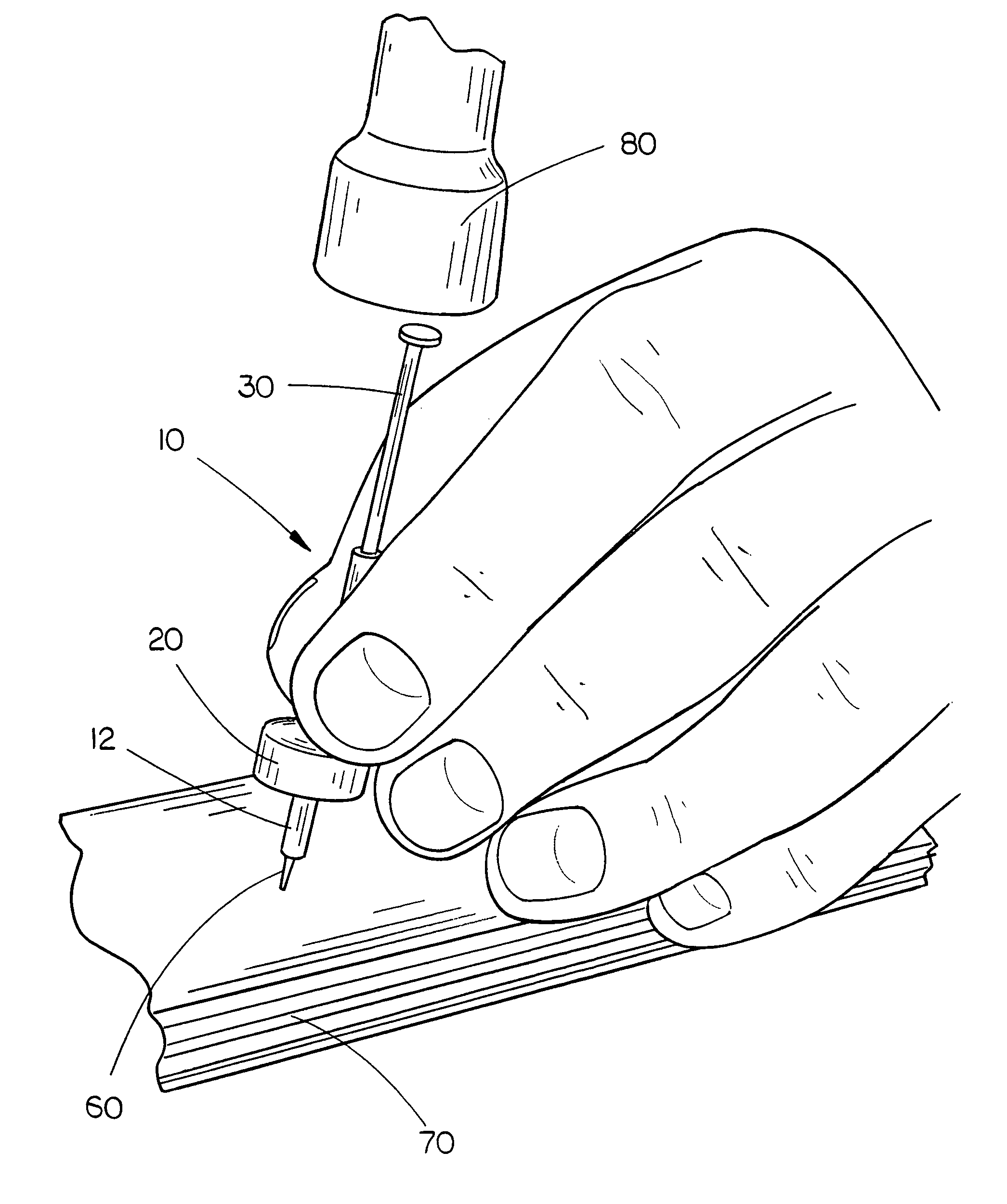
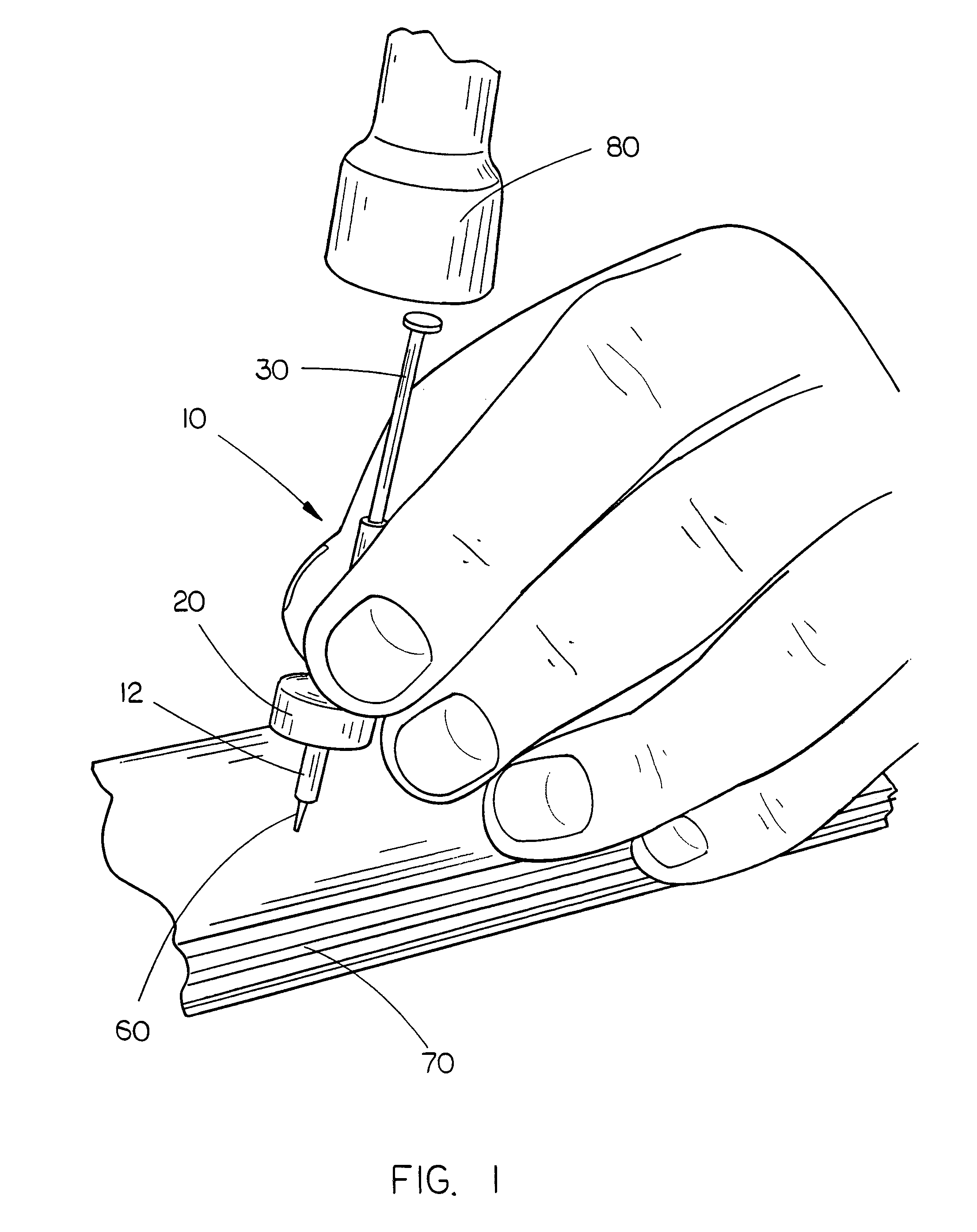
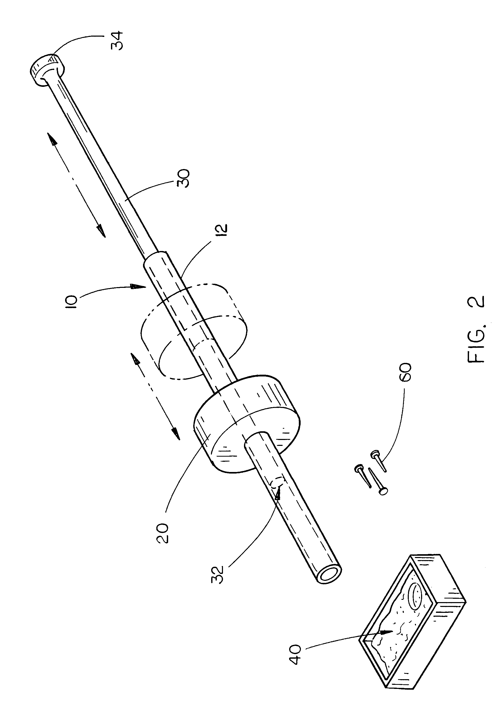
[0018]The nail holding and nail driving device 10 of the present invention is shown best in FIGS. 1-3 as including a generally cylindrical main tube 12 which, in the preferred embodiment, would have a length of approximately one to two inches, an external diameter of approximately 1 / 16 inch to ¼ of an inch and an internal diameter of approximately 0.05 inches to 0.3 inches. It is further preferred that the main tube 12 be constructed of a non-ferrous material such as aluminum, brass or copper so that the main tube 12 is generally non-magnetic. Additionally, it should be noted that the internal diameter of the main tube 12 will generally correspond to the size of the nails with which the nail holding and driving device 10 is to be used, and therefore it is expected that several different sizes of main tubes 12 may be used in connection with the present invention in order to accommodate various sizes of nails therewithin.

[0019]Frictionally mounted on the outer wall of the main tube 12...


PUM


Abstract

A nail holding and driving device includes an elongated generally non-magnetically conductive main tube and a magnet movably mounted on the outer wall of the main tube. A nail-driving rod is slidably housed within the main tube, the nail-driving rod being constructed of a magnetically conductive material and having a nail engaging and striking lower impact end face and an impact-receiving upper end. The magnet is operative to magnetize the nail-driving rod through the main tube. The nail-driving rod is operative to magnetically engage a nail to support the nail within the main tube in contact with the nail engaging and striking lower end of the nail-driving rod and drive the nail into the desired location by impact of a nail-driving device with the impact-receiving upper end of the nail-driving rod.

Description

CROSS-REFERENCE TO RELATED PATENTS[0001]This application claims the benefit of U.S. Provisional Application No. 60 / 800,820, filed May 16, 2006.BACKGROUND OF THE INVENTION[0002]1. Technical Field[0003]The present invention relates to nail positioning and driving devices and, more particularly, to a nail holding and driving device for use with very small, difficult-to-hold nails which includes a generally cylindrical main tube, a toroidal magnet movably mounted on the outer wall of the main tube and a generally cylindrical nail-driving rod which is slidably housed within the main tube, the nail-driving rod being constructed of a ferrous metal material such that the toroidal magnet magnetizes the nail-driving rod so that the rod, when encountering a metal nail, will magnetically engage the nail to support the nail within the main tube in contact with the nail-driving rod prior to the nail being inserted into the desired location by impact of a hammer or other nail-driving device with t...

Claims


Application Information

Patent Timeline
Patent Type & Authority Patents(United States)
IPC IPC(8): B25C5/06
CPCB25C1/02
Inventor HASKINS, MICHAEL LEEHUTCHISON, DONNA L.
Owner HASKINS MICHAEL LEE
Why Eureka
Try Eureka