Controlling apparatus of variable capacity type fuel pump and fuel supply system

a control apparatus and variable capacity technology, applied in the direction of fuel injection apparatus, charge feed system, electric control, etc., can solve the problems of difficult to change the drive timing, noisy, and inability to keep a common rail pressure at the desired pressure,

Inactive Publication Date: 2009-07-14
HITACHI LTD
View PDF6 Cites 18 Cited by
  • Summary
  • Abstract
  • Description
  • Claims
  • Application Information

AI Technical Summary

Benefits of technology

[0007]According to the present invention, an object thereof is to avoid the synchronization between the noise, which is caused due to driving of the high-pressure fuel pump, and the noise, which is caused due to operation of the injector, while keeping the engine under a desired operating condition.
[0008]For achieving the object mentioned above, according to the present invention, for the purpose of maintaining a predetermined time-interval between the drive timing of an injector and the drive timing of a variable capacity controlling mechanism, which is provided within a variable capacity type fuel pump, so as to eliminate the duplication or overlapping on the drive timings thereof, control of the driving timing of the variable capacity controlling mechanism is effected.
[0009]According to the present invention, it is possible to avoid the synchronization of noises (i.e., operating sounds) of the injector and the variable capacity type fuel pump, while keeping the engine under the desired operating condition with maintaining the drive timing of the injector.

Problems solved by technology

Those noises, although being not so large by itself, but sometimes could be felt to be noisy, in particular, due to the synergistic effect, when they are generated overlapping or duplicating with each other in the timing thereof.
For the injector, the drive timing of which is closely related to the operation condition of the engine, it is not easy to change the drive timing, arbitrarily.
Also, with the high-pressure fuel pump (for example, a fuel pump of a variable capacity type), having the structure of controlling the discharge flow amount by changing the drive timing thereof, it is impossible to keep a common rail pressure at a desired pressure, since the discharge flow amount is changed when the drive timing thereof is altered.

Method used


Image

  • Controlling apparatus of variable capacity type fuel pump and fuel supply system
  • Controlling apparatus of variable capacity type fuel pump and fuel supply system
  • Controlling apparatus of variable capacity type fuel pump and fuel supply system

Examples


embodiment 1

[0032]Hereinafter, explanation will be given about an embodiment of the present invention.

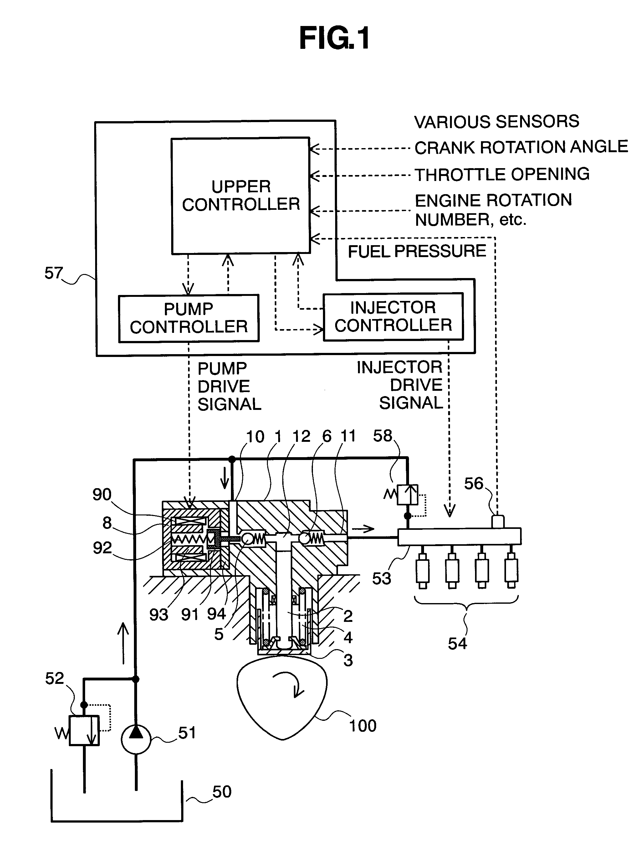
[0033]First of all, explanation will be made on the structures of a fuel supply system, which applies the variable capacity type fuel pump according to the present embodiment therein, by referring to FIG. 1. In a pump main body 1 are formed a fuel suction passage 10, a discharge passage 11, and a pressurizing chamber 12. Within the pressurizing chamber 12, a plunger 2 is slidably held and functions as a pressurizing member. In the suction passage 10 and the discharge passage 11 are provided a suction valve 5 and a discharge valve 6, respectively. The suction valve 5 and the discharge valve 6 are biased by springs in one direction, so that they act as a check valve. Also, to the suction passage 10 is connected a low-pressure valve 9.

[0034]A variable capacity control mechanism 8 is held within the pump main body 1, and is comprised of a solenoid coil 90, a rod 91, and a spring 92. The rod 91 is b...

embodiment 2

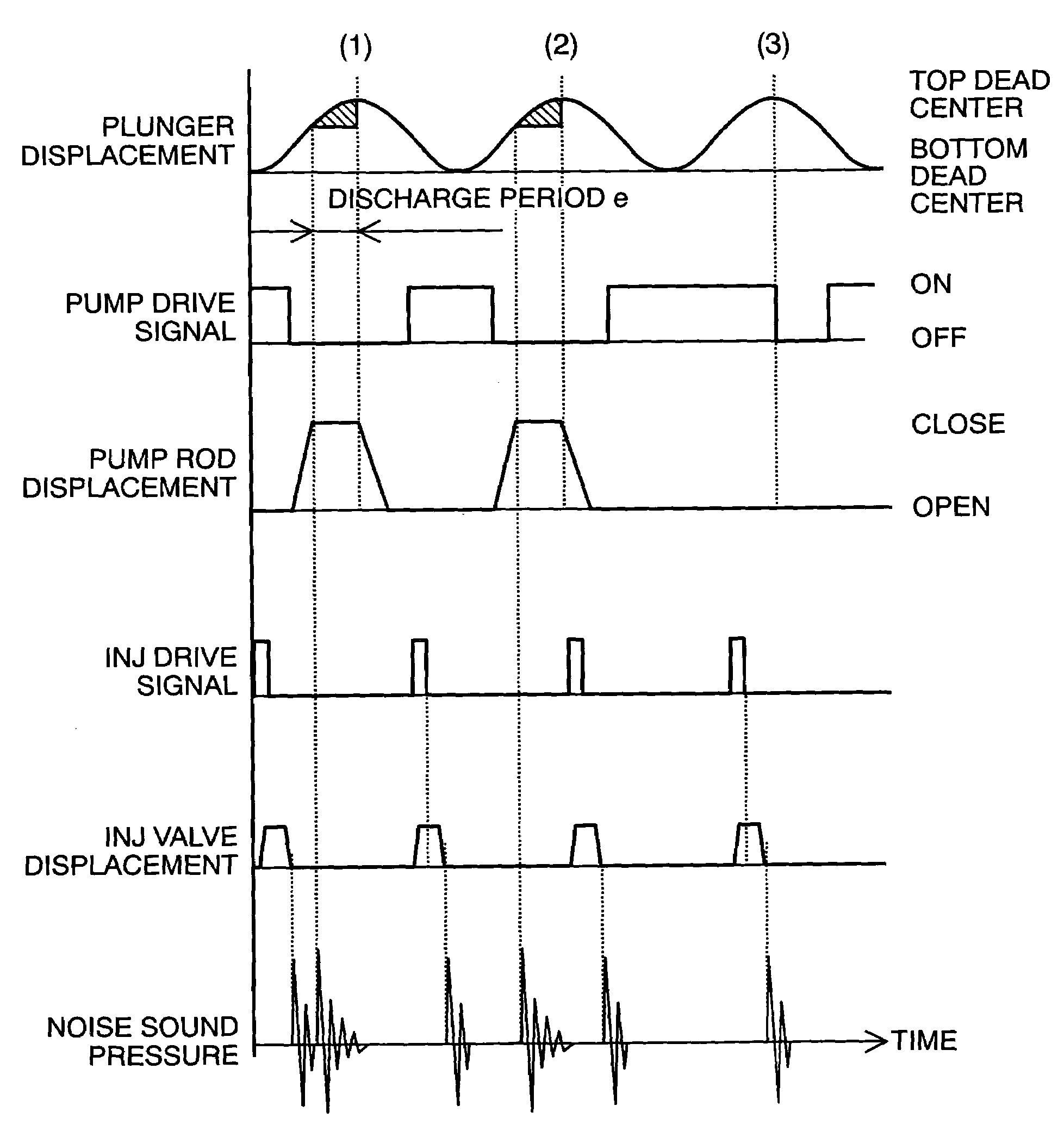
[0072]FIG. 6 shows a timing chart according to other embodiment of the present invention. The structures of the fuel supply system are similar to those of the system shown in FIG. 1.

[0073]For avoiding the noises of the pump and the injectors from overlapping on each other within the plunger cycle (3), the timing is moved forward when supplying the pump drive signal. With the pump building up, the flow rate is increased, being discharged from, when the drive timing thereof is moved forward. Accordingly, if only forward moving is made on the timing when the pump drive signal is provided for avoiding the overlapping of the noises, then the pump discharges the fuel much more than that of the desired discharge flow rate, thereby bringing about an increase of the fuel pressure within the common rail 53.

[0074]However, if reducing the flow rate discharged by shifting the timing of providing the pump drive signal backward, within the plunger cycles (1) or (2), so as to cancel the fuel discha...

embodiment 3

[0076]FIG. 7 shows a view of other embodiment.

[0077]A fuel pump 1a repeats the suction / discharge of fuel by reciprocating movement of a plunger 2a, and also controls a flow-amount control mechanism 8a, thereby controlling an amount of fuel to be discharged to a high-pressure side. The flow-amount control mechanism 8a is built up with a suction valve 5a and a rod 91a, in one body, and is biased into a direction to open the valve by way of a spring 92a. When no drive signal is provided to the flow-amount control mechanism 8a, the suction valve 5a is held closing the valve, through the biasing force of the spring 92a; therefore, the fuel pump 1a does not pressurize the fuel therein. When the drive signal is provided from the controller 57a, the suction valve 5a is biased towards the closing position of valve through magnetic sucking force, then it pressurizes the fuel within a pump chamber 12a.

[0078]The control method for the system of FIG. 7 is similar to that for the above-mentioned...


PUM


Abstract

A controlling apparatus of a variable capacity type fuel pump, for preventing noises caused due to drive of the fuel pump and noises caused due to drive of injectors from overlapping or duplicating each other in the timing thereof, wherein signals for driving the pump are reduced, or the timing thereof is shifted forward / backward, within a specific timing where the overlapping can be expected, or a specific timing where they are determined to overlap or duplicate with each other.

Description

BACKGROUND OF THE INVENTION[0001]The present invention relates to a controlling apparatus of a high-pressure fuel pump for an internal combustion engine, and in particular, it relates to a controlling method of a high-pressure fuel pump for reducing noises within the internal combustion engine.[0002]Conventionally, a controlling apparatus for a fuel pump is already known, for example, in the following Patent Document 1, which comprises a high-pressure fuel pump, for sucking fuel into a pressurizing chamber by changing the volume thereof upon basis of a relative movement of a cylinder and a plunger due to rotation of a cam, thereby sending the fuel sucked towards a fuel injection valve of an internal combustion engine under pressure, and a spill valve for opening / closing a fuel passage, which is provided between a spill passage for flowing out the fuel from the pressurizing chamber, and the pressuring chamber, whereby controlling a period when the spill valve is opened, so as to regu...

Claims


Application Information

Patent Timeline
Patent Type & Authority Patents(United States)
IPC IPC(8): F02M37/04
CPCF02D41/3845F02M2200/09F02M59/368F02D41/406F02D2200/025F02D2200/0618
Inventor TOKUO, KENICHIROUSUI, SATOSHIYAMADA, HIROYUKI
Owner HITACHI LTD
Why Eureka
Try Eureka