Vent and/or diverter assembly for use in breathing apparatus

a technology of diverter and vent, which is applied in the direction of mechanical equipment, valves, operating means/releasing devices, etc., can solve the problems of difficult to consistently duplicate the vent of the mask at the precision required to get repeatable pressure flow characteristics, and the atmosphere may create noise, so as to prevent the risk of high co2 levels and low noise

Active Publication Date: 2009-07-14
RESMED LTD
View PDF36 Cites 72 Cited by
  • Summary
  • Abstract
  • Description
  • Claims
  • Application Information

AI Technical Summary

Benefits of technology

[0012]Devices consistent with the principles of the present invention, as embodied and broadly described herein, overcome one or more of the difficulties indicated above and others by providing a device that utilizes a porous material having fine holes as vents to produce a respiratory mask having very low noise. Moreover, these features may be obtained while preventing the risk of high CO2 levels and obtaining consistent pressure flow characteristics.
[0018]At rest, the flap is typically in a closed position, thereby preventing the gas from flowing upstream from the oxygen injection cavity into the air supply cavity. When the flap is in closed position the gas in the oxygen injection cavity can vent into the atmosphere.

Problems solved by technology

An apparatus including a mask should be quiet and comfortable to encourage patient compliance with therapy; however, exhausting exhaled air from a vent into the atmosphere may create noise.
However, the inventor identified two potential problems encountered by the use of the vent including fine holes or the vent covered with finely meshed material.
The first problem may occur if the vents of the mask become blocked or clogged with debris.
The blocked vents reduce airflow through the vents, which could cause a high level of CO2 to accumulate in the mask and thereby create a safety concern to the user.
The second problem may occur if the vents are manufactured with the intent of obtaining repeatable pressure flow characteristics, because it is difficult to consistently duplicate the vents of the mask at a precision required to get repeatable pressure flow characteristics.

Method used


Image

  • Vent and/or diverter assembly for use in breathing apparatus
  • Vent and/or diverter assembly for use in breathing apparatus
  • Vent and/or diverter assembly for use in breathing apparatus

Examples


Embodiment Construction

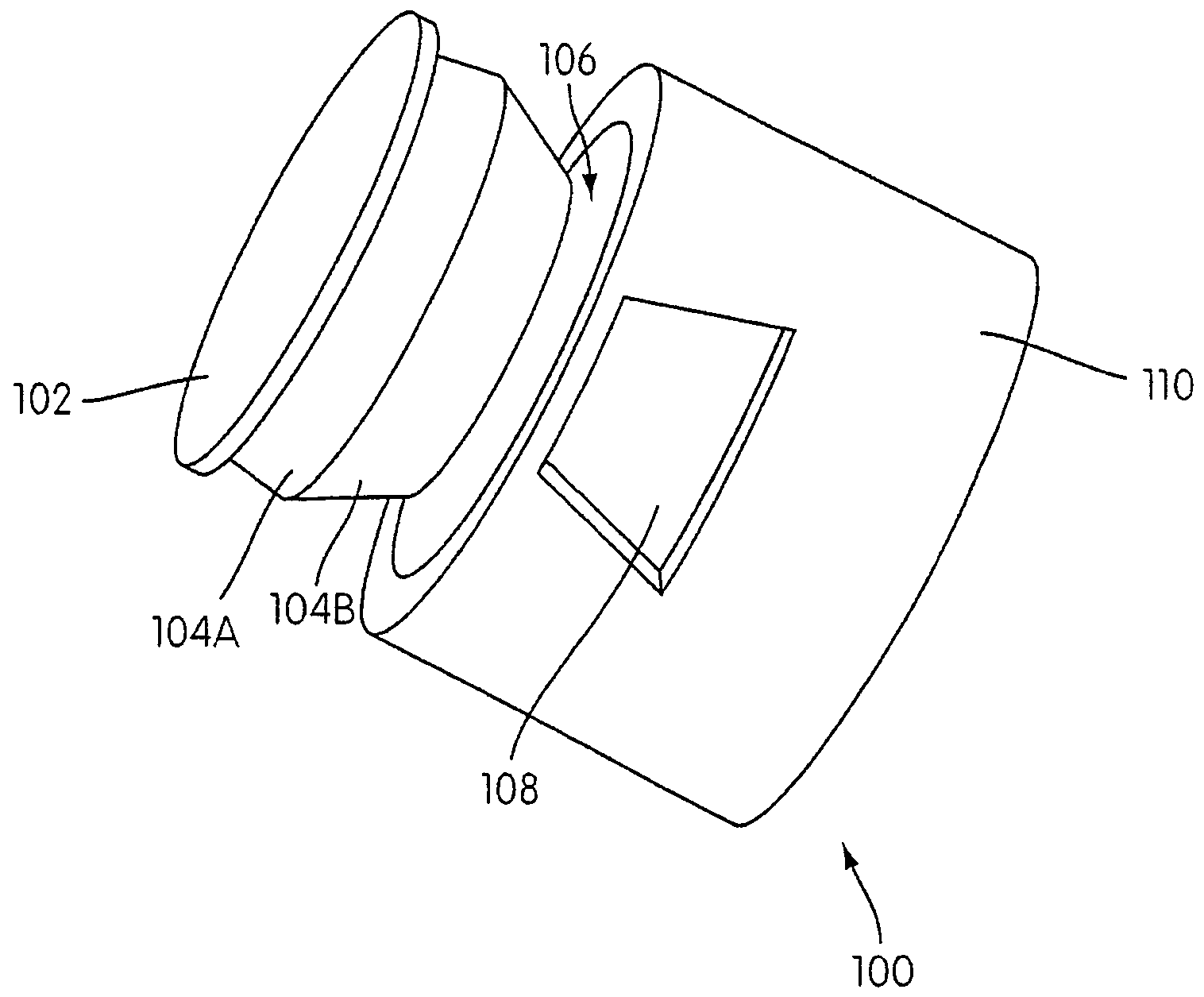
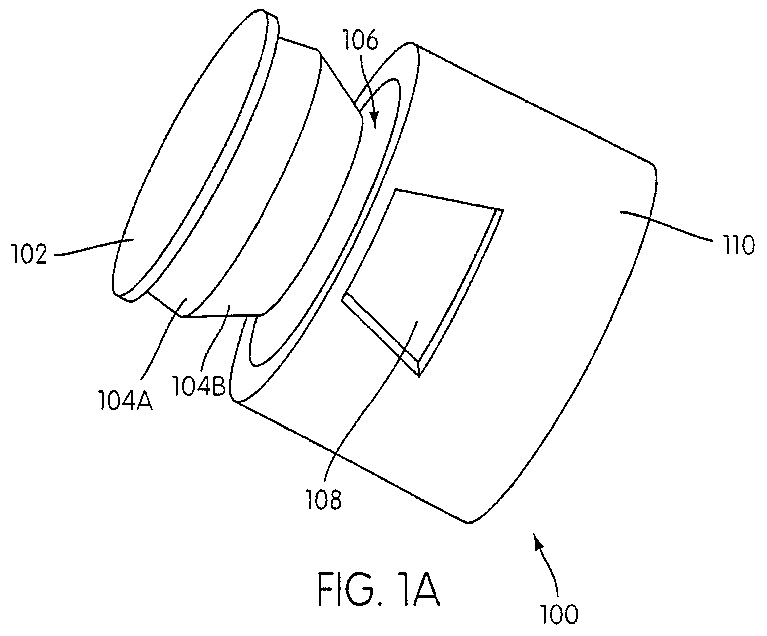
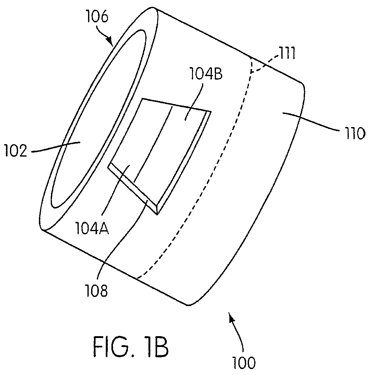
[0062]FIG. 1A illustrates an exploded view of a vent assembly 100 of a respiratory mask frame 110 in accordance with a first embodiment of the present invention. The mask frame 110 includes at least one side vent 108, a main vent 106, a bellows portion 104, and a disk portion 102 attached to an end of the bellows portion 104. Bellows portion 104 may be, for example, constructed from a silicone material or other suitable flexible material known in the art. The bellows portion 104 can have a first bellows section 104A and a second bellows section 104B constructed and arranged to provide a biasing force. Bellows portion 104 may also be substituted by a biasing member such as a spring that is assembled to the mask frame 110. Disk portion 102 may be, for example, a porous plate having multiple, finely-spaced holes and / or a piece of finely meshed fabric.

[0063]As illustrated in FIG. 1A, the disk portion 102 may be attached to the top of bellows portion 104 such that a biasing force produce...


PUM


Abstract

A vent assembly for use with a respiratory mask of the type used in CPAP treatment includes a porous disk portion that is attached to a biasing member such that the disk portion is maintained in a substantially sealed position against a main vent to minimize airflow through at least one side vent of the vent assembly. Debris build-up on the disk portion can cause the biasing member to deflect to provide an additional path for airflow through the at least one side vent. In another embodiment, the vent assembly can also include an anti-asphyxia feature to provide an airflow path from the environment to the user. An oxygen diverter valve may be disposed between the breathing apparatus flow generator and an oxygen injection port.

Description

CROSS-REFERENCE TO RELATED APPLICATION[0001]This application claims the benefit of U.S. Provisional Application No. 60 / 479,188, filed Jun. 18, 2003, incorporated herein by reference in its entirety.BACKGROUND OF THE INVENTION[0002]1. Field of the Invention[0003]The invention generally relates to the field of treatment for breathing disorders. More specifically, the present invention relates to the vent of a respiratory mask for ventilatory treatment or assistance.[0004]The present invention also relates to an oxygen diverter valve used in systems where air or another breathable gas is mixed with oxygen. The valve may be used in conjunction with the vent. The valve has been developed primarily for use between a gas delivery apparatus for delivery of breathable gas and an oxygen port. One goal is that that when airflow is stopped the valve closes and prevents oxygen to flow upstream into the flow generator.[0005]The valve is also suitable for use in other gas delivery systems, such as...

Claims


Application Information

Patent Timeline
Patent Type & Authority Patents(United States)
IPC IPC(8): A62B9/02A61M16/06A61M16/12A61M16/20A62B7/10A62B18/08
CPCA61M16/06A61M16/0057A61M16/208A61M16/12A61M2202/0208A61M16/0825A61M2205/0216A61M16/0611A61M16/0616A61M2202/0225A61M2205/42A61M2202/0085A61M16/0683A61M16/0816
Inventor SMITH, IAN MALCOLMDANTANARAYANA, MUDITHA PRADEEPJANIAK, MICHAEL THOMAS
Owner RESMED LTD
Why Eureka
Try Eureka