Digital broadcast receiving apparatus and receiving method

a digital broadcast and apparatus technology, applied in the field of digital broadcast receiving apparatus and receiving method, can solve the problems of service person responding, automatic improvement of deterioration, and no how, and achieve the effect of affecting the deterioration of the receiving characteristics of the antenna

Inactive Publication Date: 2009-07-14
SONY CORP
View PDF8 Cites 28 Cited by
  • Summary
  • Abstract
  • Description
  • Claims
  • Application Information

AI Technical Summary

Benefits of technology

[0010]Thus, there is, conventionally, only a measure that a servicing person responds thereto separately. In this case, it is possible to improve the deterioration in the receiving characteristics by adjusting a value of register in the demodulator using a special mode (servicing mode) that is operable by the servicing person, but it has a problem in a cost such that the servicing person responds thereto separately.
[0012]This invention has thus an object to provide an apparatus and a method for receiving digital broadcast signal by which a factor in deterioration for receiving characteristics of an antenna can be automatically determined and deterioration for receiving characteristics due to phase noise of a local oscillator in a frequency converter accompanied with the antenna and parasitic oscillation thereof can be automatically improved.
[0014]For example, the measure mode includes a first measure mode responding to a case where carrier / noise ratio is low; a second measure mode for improving deterioration for receiving characteristics due to phase noise of local oscillator in a frequency converter accompanied with the antenna; and a third measure mode for improving deterioration for receiving characteristics due to parasitic oscillation of the local oscillator in the frequency converter accompanied with the antenna.
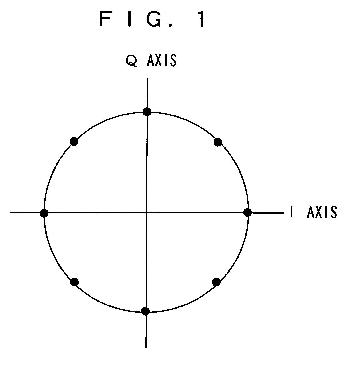
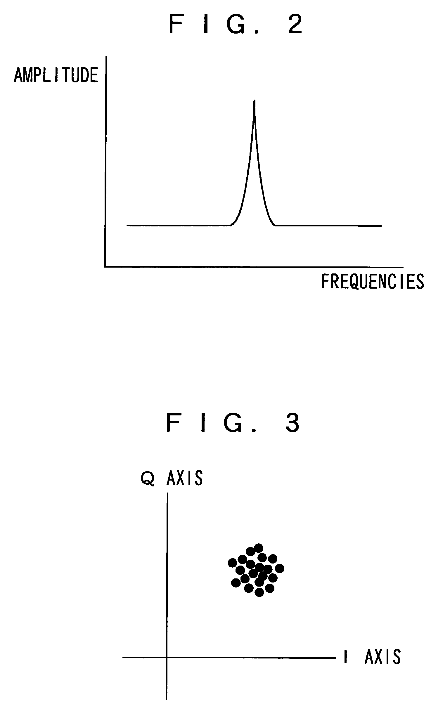
[0016]According to the present invention, the C / N-value-calculating circuit, the phase-noise-amount-calculating circuit, and the bit-error-rate-measuring circuit are provided; when receiving the signal, a received signal sent from the antenna is orthogonally detected to a baseband signal; an average value of amplitude in radial direction of signal points of phase mapping of the obtained baseband signal is then measured to calculate a C / N value for the received signal; an average value of amplitude in circumferential direction of signal points of the phase mapping of the baseband signal is measured to calculate an amount of phase noise of the received signal; a bit-error rate of transport stream that is given by demodulating the baseband signal is then measured; a factor in deterioration for receiving characteristics of the antenna is determined based on these results; and a desired measure mode is set based on the determination result thereof. This allows a factor in deterioration for receiving characteristics of the antenna to be automatically determined and the deterioration for receiving characteristics due to phase noise of local oscillator in a frequency converter accompanied with the antenna and parasitic oscillation thereof to be automatically improved.

Problems solved by technology

In the conventional apparatus for receiving digital satellite signal as described above, however, there is no how to automatically determine a factor in the deterioration of its receiving characteristics, so that a best measure for improving these deteriorations automatically cannot be taken.
In this case, it is possible to improve the deterioration in the receiving characteristics by adjusting a value of register in the demodulator using a special mode (servicing mode) that is operable by the servicing person, but it has a problem in a cost such that the servicing person responds thereto separately.
Further, if receiving characteristics is deteriorated due to phase noise in the local oscillator of frequency converter accompanied with the antenna and parasitic oscillation thereof, it is possible to respond thereto by purchase a new antenna in a most case, but it has such a problem that a cost therefor is requested or the replacement thereof cannot be easily carried out in a case of community antenna system.

Method used


Image

  • Digital broadcast receiving apparatus and receiving method
  • Digital broadcast receiving apparatus and receiving method
  • Digital broadcast receiving apparatus and receiving method

Examples


Embodiment Construction

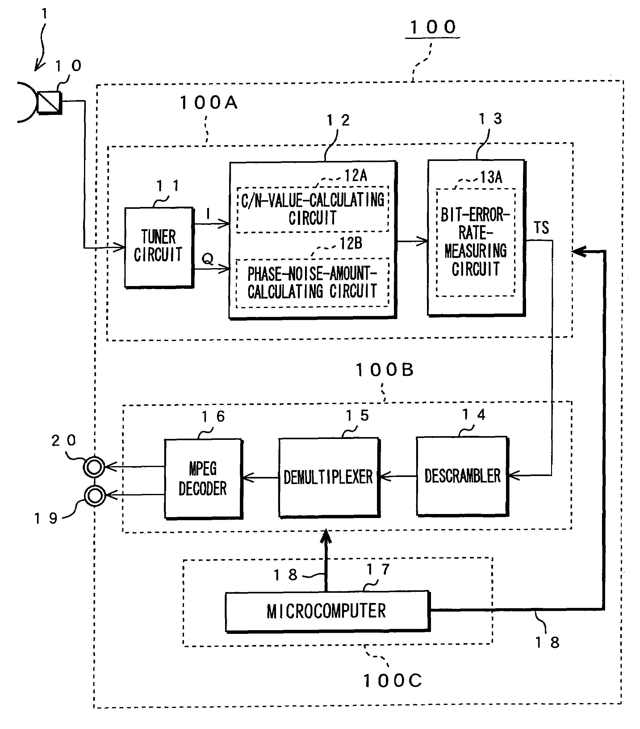
[0026]The following will describe one embodiment of the present invention with reference to drawings. FIG. 8 shows a configuration of an apparatus 100 for receiving digital broadcast signal as an embodiment of the invention. This apparatus 100 for receiving digital broadcast signal is a receiver for receiving BS digital signal.

[0027]As shown in FIG. 8, the apparatus 100 for receiving digital broadcast signal has a front-end portion 100A, back-end portion 100B, and a controlling portion 100C. The front-end portion 100A has a tuner circuit 11, a demodulation circuit 12, and an error-correction circuit 13. The back-end portion 100B has a descrambler 14, a demultiplexer 15, and an MPEG decoder 16. The controlling portion 100C has a microcomputer 17.

[0028]The tuner circuit 11 is a circuit in which target broadcast signal is tuned from broadcast signal (BS-IF signal) that has been sent from an antenna 1 through a frequency converter (LNB) 10 and amplitude processing or the like is perform...


PUM


Abstract

A factor in deterioration of receiving characteristics of an antenna is automatically determined and automatically improved. In an apparatus for receiving digital broadcast signal, when receiving the signal, a received signal sent from the antenna 1 is orthogonally detected to a baseband signal; an average value of amplitude in radial direction of signal points of phase mapping of the baseband signal is then measured to calculate a C / N value for the received signal; an average value of amplitude in circumferential direction of signal points of the phase mapping of the baseband signal is measured to calculate an amount of phase noise of the received signal; a bit-error rate of transport stream that is given by demodulating the baseband signal is then measured; a factor in deterioration for receiving characteristics of the antenna is determined based on these results; and a desired measure mode is set based on the determination result thereof.

Description

TECHNICAL FIELD[0001]The present invention relates to an apparatus and a method for receiving digital broadcast signal, which receive digital satellite broadcast signal via an antenna.BACKGROUND ART[0002]A television broadcast receiver has conventionally been available to receive an analog broadcast signal such as a VHF / UHF broadcast signal via terrestrial broadcast and a signal for broadcasting satellite (BS) utilizing any broadcast satellite. A television broadcast receiver that can receives a BS digital signal or a communication satellite (CS) digital signal utilizing any broadcast satellite has recently been put to practical use. When using such the television broadcast receiver, an antenna that has been used for conventional BS analog may have been often used as it is for receiving BS digital signal.[0003]For conventional BS analog there has been strong immunity against FM residual noise because of its FM modulation so that even if an antenna having a large amount of phase nois...

Claims


Application Information

Patent Timeline
Patent Type & Authority Patents(United States)
IPC IPC(8): H04N5/44H04B17/00H04L1/20H04L27/22
CPCH04L1/206H04N21/4382H04N5/4401H04L27/22H04N21/426H04N7/015
Inventor NAKAMURA, NAOHITO
Owner SONY CORP
Why Eureka
Try Eureka