
Ion Generating Element, Ion Generator and Neutralizer

Inactive Publication Date: 2009-08-20
NAT INST OF ADVANCED IND SCI & TECH +1
View PDF5 Cites 23 Cited by
  • Summary
  • Abstract
  • Description
  • Claims
  • Application Information

AI Technical Summary

Benefits of technology

[0009]Related art as disclosed in Patent documents 1 to 3 locally discharges by applying a high voltage power supply between a discharge electrode and an induction electrode via a dielectric body so as to generate ions. As a result, the related art has a flat shape without a physically acuminate structure. The employment of the local discharge makes it possible to generate an equivalent amount of ions with a lower voltage and less power consumption than the needle-shaped ion generating electrode. Furthermore, forming an insulation protecting layer formed by a coating layer on the discharge electrode makes possible improvements in deterioration of the electrode, current leakage toward a creepage and maintainability. As a result, the problem the needle-shaped ion generating electrode has is alleviated.
[0010]However, the ion generation by the electrode structure formed via the dielectric body as described above comes to have high impedance between the electrodes unless a relatively high frequency electric power is supplied. Accordingly, efficiency is remarkably lowered, rendering generation of ions impossible.

Problems solved by technology

Accordingly, there is a problem that space for constituting ion generation is constrained and thus limitations on size reduction of an efficient ion generator and neutralizer arise.
In addition, the needle-shaped ion generating electrode over long-term use induces corona discharge with difficulty due to influences of buildup of dust and abrasion of physical sputtering, so that ion generating efficiency tends to be reduced.
This also results in reduction of ion generating efficiency.
Since the maintenance work is the cleaning of an interior of the structure with the acuminate portion, which is also a part where a high voltage is applied, the work is dangerous and troublesome.

Method used


Image

  • Ion Generating Element, Ion Generator and Neutralizer
  • Ion Generating Element, Ion Generator and Neutralizer
  • Ion Generating Element, Ion Generator and Neutralizer

Examples


Embodiment Construction

[0061]Details of an ion generating element of the present invention are described below with reference to the accompanying drawings.

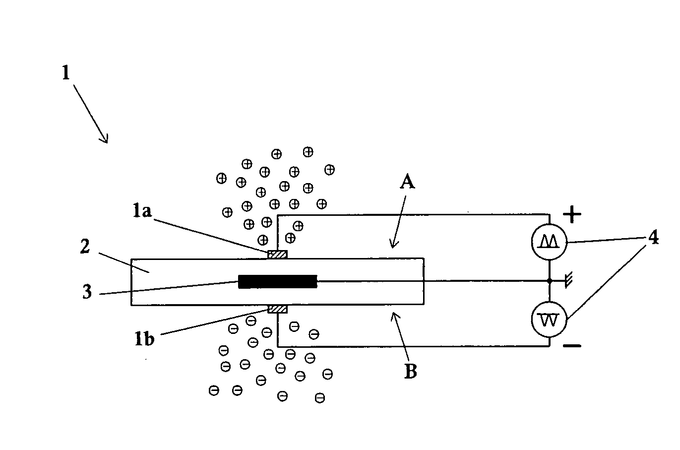
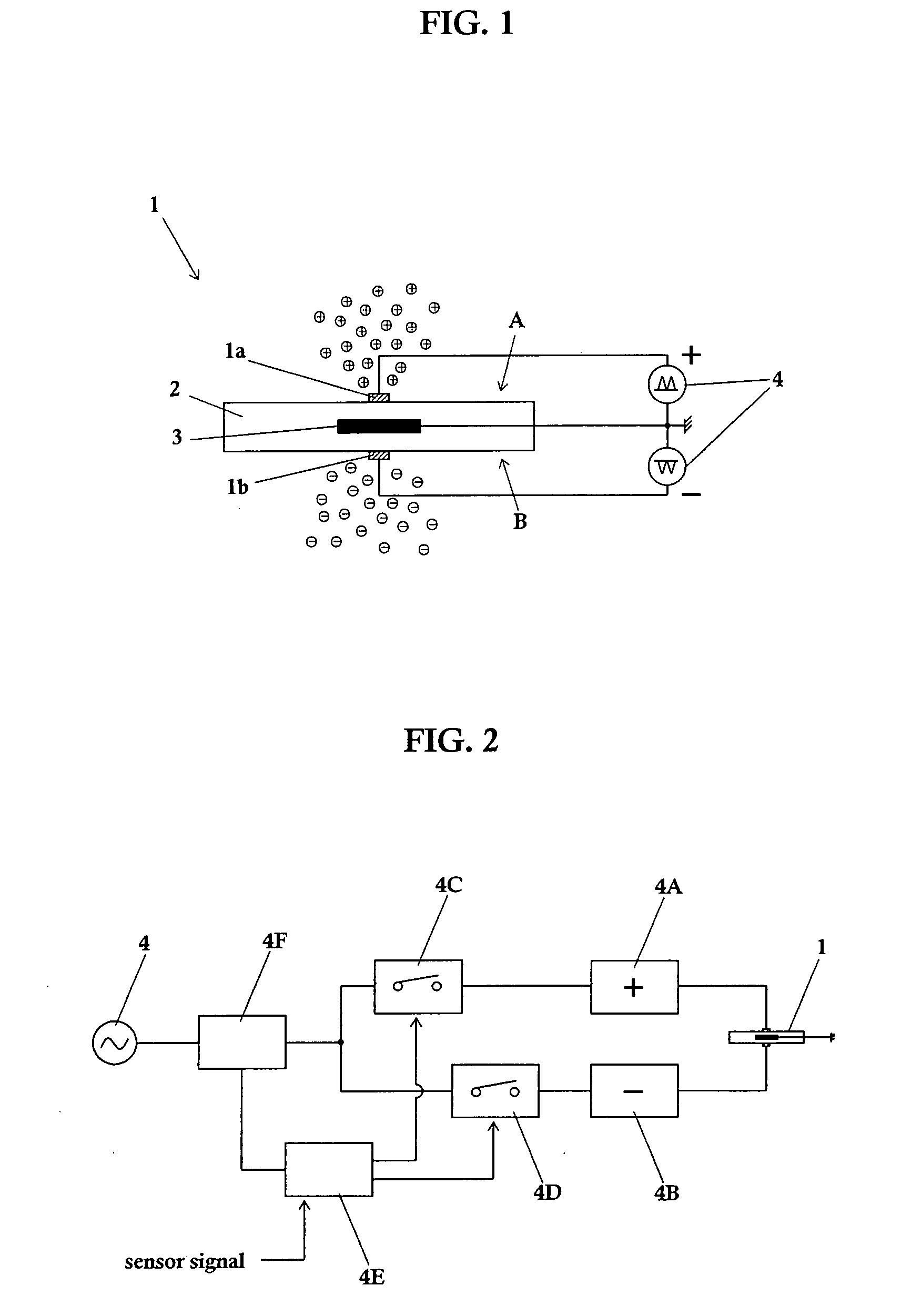
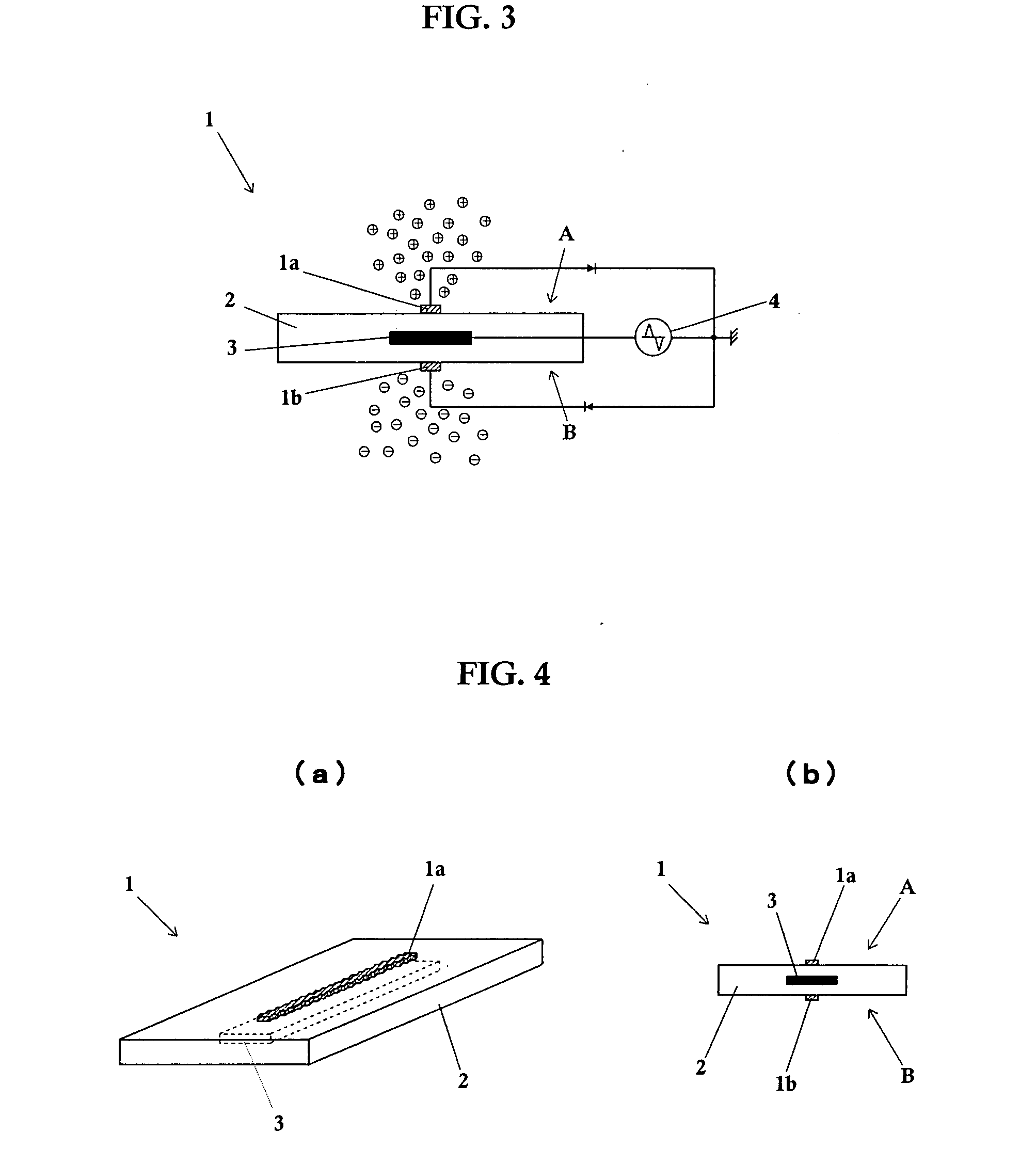
[0062]An ion generating element according to the present invention has a constitution of generating positive ions and negative ions on the different faces of the dielectric in which a dielectric body with at least two faces, at least two discharge electrodes arranged on at least two faces of the dielectric and an induction electrode provided inside of the dielectric and subjected to an action of at least the two discharge electrodes are provided.

[0063]More specifically, as shown in FIG. 1, an ion generating element 1 includes a dielectric body 2 with two faces of a front face A and a back face B. The front face A is formed with a discharge electrode 1a and the back face B is formed with a discharge electrode 1b by micromachining. Inside of the dielectric body 2, an induction electrode 3 is provided so as to be opposed to the discharge electrodes 1a and ...


PUM


Abstract

An ion generating element capable of cost reduction and space saving while exhibiting a high generation efficiency of positive ions and negative ions and stabilized generation capacity with less variation, and an ion generator and a neutralizer employing it. The ion generating element comprises a dielectric body having at least two faces, at least two discharge electrodes arranged on the at least two faces of the dielectric body, and an induction electrode arranged in the dielectric body and subjected to the action of the at least two discharge electrodes and is characterized in that positive ions and negative ions are generated on the body, and ions are generated from the at least two faces of the dielectric body through discharge generated because of the potential difference between the discharge electrode of the ion generating element and the induction electrode when a drive voltage is applied between them.

Description

TECHNICAL FIELD[0001]The present invention relates to an ion generating element, an ion generator and a neutralizer, and in particular, to an ion generating element which is capable of preventing neutralization of positive ions and negative ions generated on fine electrodes and generating ions efficiently and moreover includes a simple electrode structure by having an induction electrode in common, and an ion generator and a neutralizer with the use of the element.BACKGROUND ART[0002]Of general conventional ion generators and neutralizers, a conventional neutralizer, for example, applies a high voltage to an acuminate needle-shaped ion generating electrode by a high voltage power supply so as to induce corona discharge, thereby ionizing air. Since the needle-shaped ion generating electrode needs to induce corona discharge efficiently between an opposed ground electrode and itself, a certain insulation distance needs to be ensured. Accordingly, there is a problem that space for const...

Claims


Application Information

Patent Timeline
IPC IPC(8): H01T23/00
CPCH01T23/00H01T19/04H05F3/04
Inventor SETO, TAKAFUMIHIRASAWA, MAKOTOTSUJI, MASAAKIOKUYAMA, AKIRASAITO, SUSUMU
Owner NAT INST OF ADVANCED IND SCI & TECH
Learn More