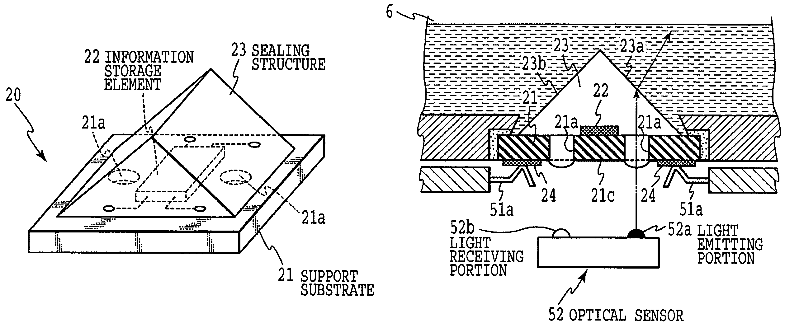
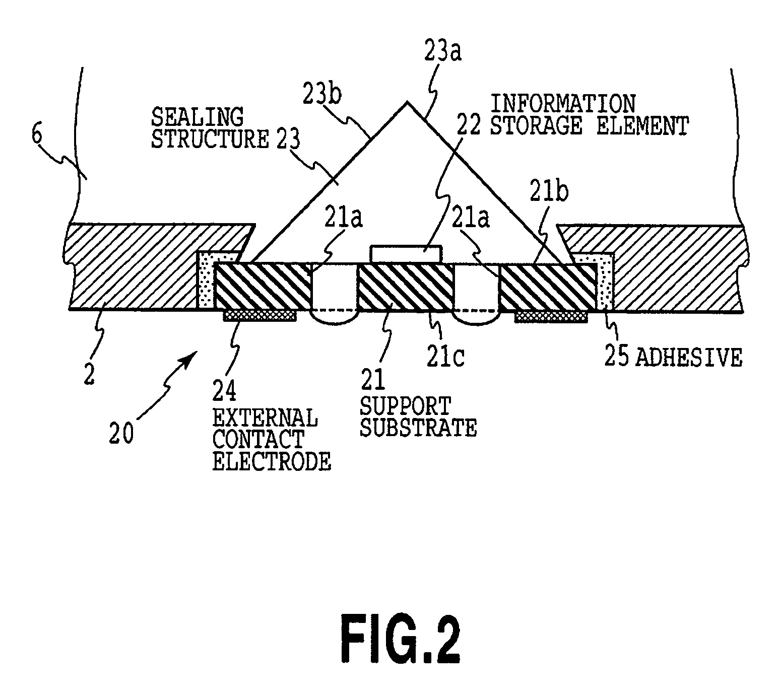
[0023]It is an object of the present invention to make it possible to detect information on ink accommodated in an ink tank using such a simple configuration as is applicable to a small-sized ink tank and to simply and reliably store the detected information. To accomplish this object, an ink remaining amount detecting module according to the present invention is mounted in an ink tank used for ink jet printing in order to detect the amount of ink remaining in the ink tank. The ink remaining amount detecting module comprises a support substrate having a site which transmits light, a nonvolatile information storage means provided on the support substrate and to and from which information can be written and read, a sealing structure provided on the support substrate so as to cover the information storage means and the site transmitting light, the sealing structure transmitting light and being shaped like a prism, and information transmitting means provided on the support substrate to receive external information on the ink remaining amount, write the information to the information storage means, and transmit the information written to the information storage means to an external device. In the ink remaining amount detecting module according to the present invention, the site of the support substrate transmitting light may be a plurality of through-holes penetrating the support substrate. In the ink remaining amount detecting module according to the present invention, the support substrate itself may be composed of a light transmissive member. In the ink remaining amount detecting module according to the present invention, the information transmitting means may be external contact electrodes provided on a surface of the support substrate which is different from that on which the information storage means and the sealing structure are provided, the external contact electrodes being electrically connected to the information storage means. In the ink remaining amount detecting module according to the present invention, the information transmitting means may have an antenna portion provided on a surface of the support substrate which is different from that on which the information storage means and the sealing structure are provided, the antenna portion utilizing high-frequency electromagnetic induction or a high-frequency electric wave to transmit and receive information in a non-contact manner. In the ink remaining amount detecting module according to the present invention, a reflector reflecting light may be formed on a part of the support substrate.
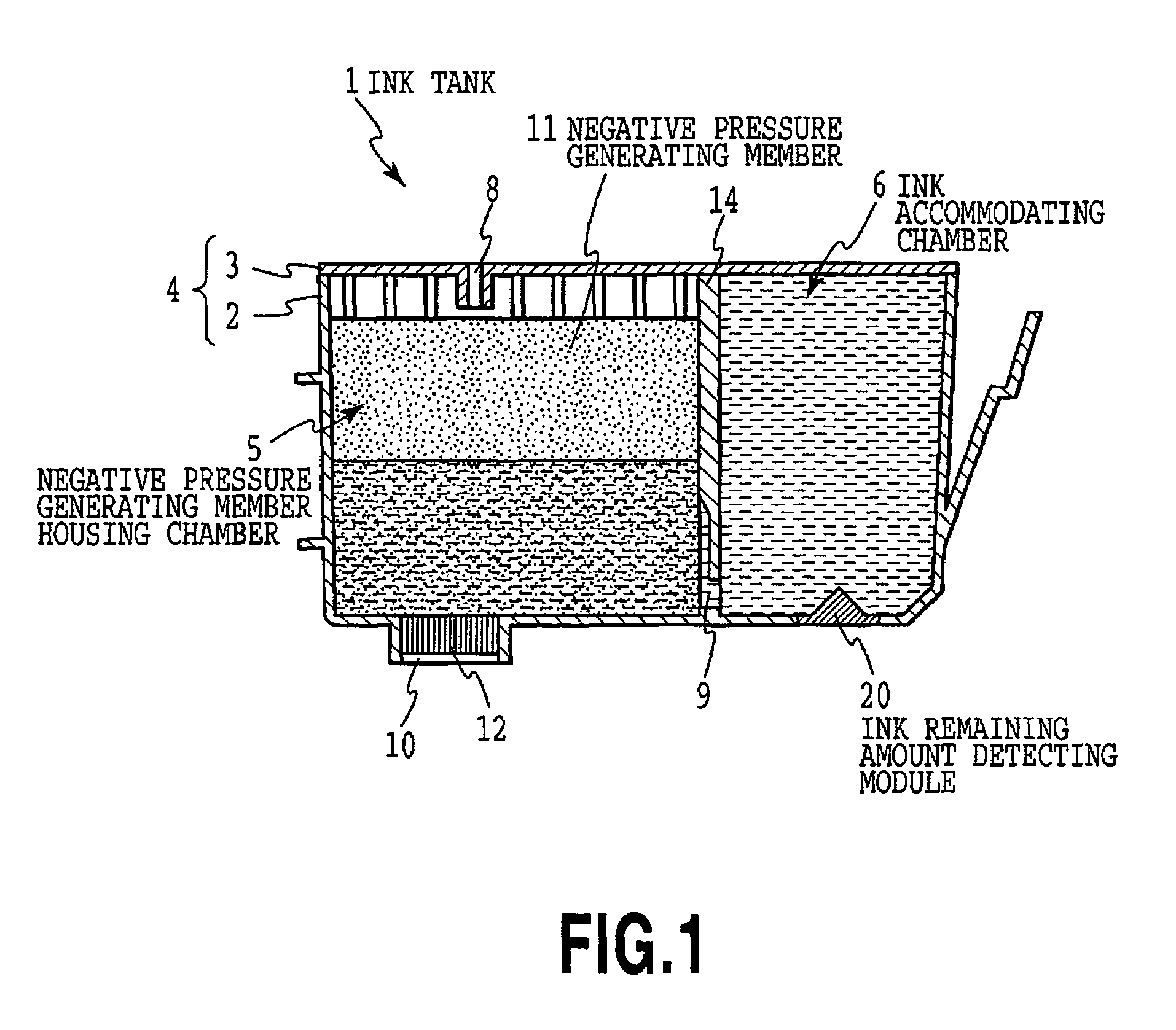
[0024]According to the ink remaining amount detecting module according to the present invention, the information storage means and the information transmitting means are provided on the support substrate. Further, the sealing structure, at least partly shaped like a prism, provides sealing so that the information storage means does not come into direct contact with ink or gas. Thus, the ink remaining amount detecting module has a function for optically detecting the ink remaining amount. This serves to provide a compact ink remaining amount detecting module with a simple configuration which is suitably mounted in a small-sized ink tank. The ink remaining amount detecting module according to the present invention also has the nonvolatile information storage means. Accordingly, information on the ink remaining amount can be simply and reliably stored in the ink remaining amount detecting module itself. An ink tank according to the present invention has an ink accommodating chamber in which ink is accommodated, and an ink supply port through which the ink in the ink accommodating chamber is supplied to a print head. The ink tank according to the present invention comprises an ink remaining amount detecting module including a support substrate having a site which transmits light, nonvolatile information storage means provided on the support substrate and to and from which information can be written and read, a sealing structure provided on the support substrate so as to cover the information storage means and the site transmitting light, the sealing structure transmitting light and being shaped like a prism, and information transmitting means provided on the support substrate to receive external information on the ink remaining amount, write the information to the information storage means, and transmit the information written to the information storage means to an external device. The ink tank according to the present invention further has a housing member constituting an outer wall of the ink accommodating chamber and the ink supply port. In the ink tank according to the present invention, it is characterized that the ink remaining amount detecting module is mounted in the housing member so that the sealing structure provided on the support substrate is exposed to the ink accommodating chamber and that another surface on the support substrate is exposed to an outer surface of the housing member. In the ink tank according to the present invention, the ink may be accommodated so that the ink contacts the sealing structure and that the ink having contacted the sealing structure reaches the ink supply port. In the ink tank according to the present invention, an opening may be formed in the housing member, and the ink remaining amount detecting module may be fixedly fitted into the opening in the housing member.
[0025]The above ink remaining amount detecting module according to the present invention is mounted in the ink tank according to the present invention. This makes it possible to detect the ink remaining amount and to provide the ink tank with information on the ink remaining amount, without hindering the ink tank from downsizing.
[0028]With the method for manufacturing an ink tank according to the present invention, the information indicating the presence of ink is written to the information storage means of the ink remaining amount detecting module after ink has been filled. Accordingly, information on the amount of ink remaining in the ink tank is simply and reliably stored in the ink tank. This also avoids the inconsistency between information detected by the ink remaining amount detecting module and information held in the information storage means, the inconsistency possibly occurring if the used ink tank is utilized after it has been filled with ink.
[0029]According to the present invention, in the ink remaining amount detecting module, the information storage element and the information transmitting means are provided on the support substrate, and the sealing structure sealing the information storage element has, at least partly, a prism function for detecting the ink remaining amount. This makes it possible to detect the amount of ink remaining in the ink tank using a compact and simple configuration and to simply and reliably provide the ink tank with information on the ink remaining amount.
[0030]Further, with the method for manufacturing an ink tank according to the present invention, the amount of ink remaining in the ink tank can be determined using only the ink tank without the need to install the ink tank in the ink jet printing apparatus. Furthermore, if the ink tank is to be reused, it is possible to eliminate the inconsistency between the information detected by the ink remaining amount detecting module and the information held in the information storage means.

