
Blow torch burner

a burner and blow torch technology, applied in the direction of burners, combustion types, fuel supply regulation, etc., can solve the problems of unpredictably increasing or decreasing the length of the flame produced, and the first-time user may not be quickly adapted to the dual-function of the control knob

Inactive Publication Date: 2009-07-28
LIN ARLO
View PDF11 Cites 5 Cited by
  • Summary
  • Abstract
  • Description
  • Claims
  • Application Information

AI Technical Summary

Benefits of technology

"The present invention is a blow torch burner that reduces the risk of accidentally changing the amount of combustion gas during ignition. It includes a reservoir for holding combustion gas and a valve seat with an ignition apparatus and a moveable rod to control the amount of combustion gas fed into the valve seat. An adjusting member is connected to the rod and can move with respect to the valve seat and a compartment where an actuator is located to actuate the ignition apparatus and ignite the combustion gas. The technical effect of this invention is to minimize the risk of accidental manipulation of the adjusting member during operation of the actuator."

Problems solved by technology

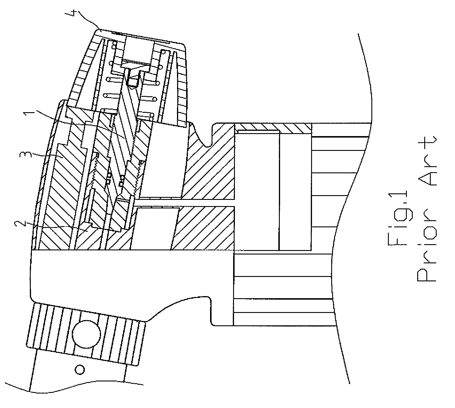
However, a problem arises when the user presses the control knob 4 to actuate ignition apparatus 3, due to the fact being the user is likely to accidentally rotate the control knob 4.
Therefore, length of the flame produced can be unpredictably increased or decreased, which is dangerous.
Another problem is that a first-time user may not be quickly adapted to the dual-function of the control knob 4.

Method used


Image

  • Blow torch burner
  • Blow torch burner
  • Blow torch burner

Examples


Embodiment Construction

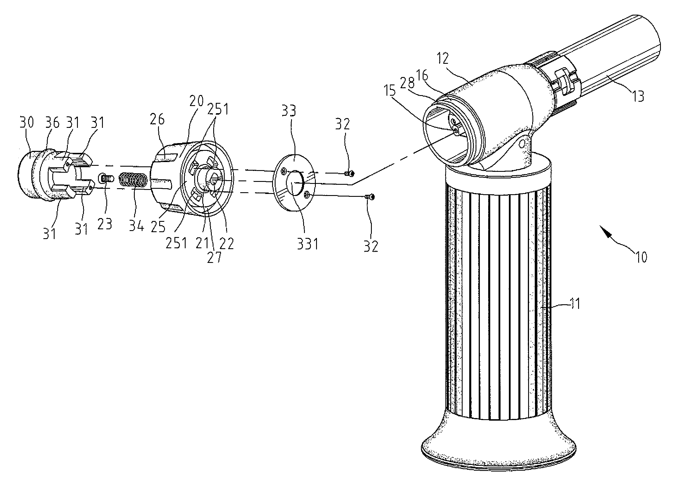
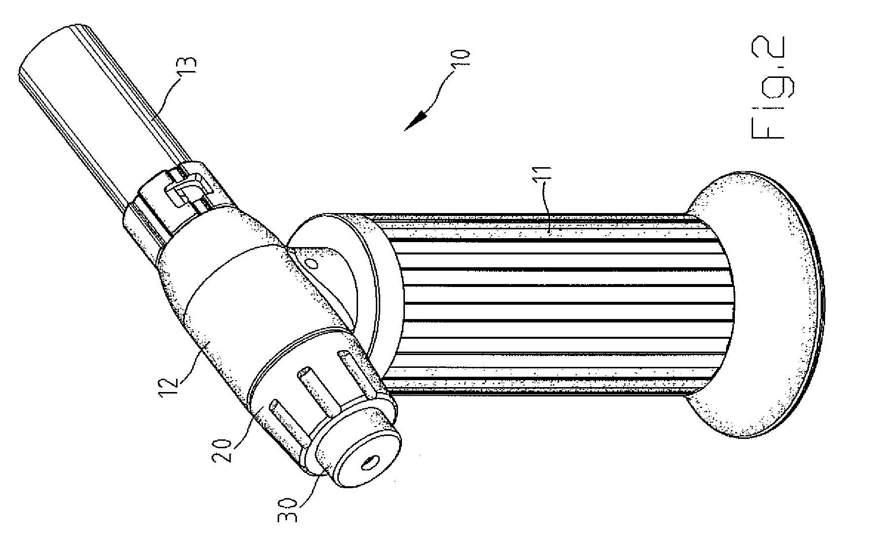
[0019]Referring to FIGS. 2 through 4, a blow torch burner 10 utilizes combustion gas in which the combustion gas is maintained in a reservoir 11 connected thereto. The blow torch burner 10 has a valve seat 12 having an ignition apparatus 14 for igniting the combustion gas and thereafter producing the flame. The flame is discharged from a nozzle 13 that locates in advance of the valve seat 12. The blow valve seat 12 further has a rod 15 therein. The rod 15 is longitudinally moveable in the valve seat 12 and therefore dynamically control amount of combustion gas fed into the valve seat 12. In addition, the rod 15 is engaged with an adjusting member 20, which may be rotated by the user for operatively moving the rod 15. More specifically, the rod 15 includes a portion being received in a non-circular orifice 22 of a first joint 21, in which the first joint 21 extends from a side of a wall portion 25 defined by the adjusting member 20. The wall portion 25 is transversely disposed within...


PUM


Abstract

A blow torch burner which utilizes combustion gas in which the combustion gas is maintained in a reservoir connected thereto. The blow torch burner has a valve seat having an ignition apparatus and a moveable rod therein. An adjusting member includes a first joint engaged with the rod such that said adjusting member is moveable with respect to said valve seat and a compartment. An actuator is slidably moveable in the compartment and is adapted to actuate said ignition apparatus.

Description

BACKGROUND OF THE INVENTION[0001]1. Field of the Invention[0002]The present invention relates to a blow torch burner.[0003]2. Description of the Related Art[0004]Referring to FIG. 1, a conventional blow torch includes an adjusting member 2 in which a rod 1 is disposed therein, and, the rod 1 can be longitudinally moved by rotating a control knob 4 connected thereto for controlling the amount of combustion gas flown into the adjusting member 2. In addition, by pressing the control knob 4, the control knob 4 can actuate an ignition apparatus 3 for igniting the combustion gas and therefore producing the flame.[0005]Although by manipulating the control knob 4, the aforementioned actions can be performed. However, a problem arises when the user presses the control knob 4 to actuate ignition apparatus 3, due to the fact being the user is likely to accidentally rotate the control knob 4. Therefore, length of the flame produced can be unpredictably increased or decreased, which is dangerous...

Claims


Application Information

Patent Timeline
Patent Type & Authority Patents(United States)
IPC IPC(8): F23D14/28
CPCF23D14/28F23N1/007F23D14/465F23N2035/24F23N2235/24
Inventor LIN, ARLO
Owner LIN ARLO
Learn More