Supplementary transformer cooling in a reactive power compensation system

a technology of reactive power compensation and transformer cooling, which is applied in the direction of transformer/inductance cooling, transformer/inductance details, electrical equipment, etc., can solve the problems of voltage instability, voltage collapse, voltage instability on the grid, etc., to reduce ambient noise, facilitate airflow direction, and prevent airflow from dispersing

Active Publication Date: 2009-07-28
AMERICAN SUPERCONDUCTOR
View PDF12 Cites 20 Cited by
  • Summary
  • Abstract
  • Description
  • Claims
  • Application Information

AI Technical Summary

Benefits of technology

[0018]With this arrangement, supplementary cooling is provided to the transformer at no additional cost, since the supplementary cooling is provided by fans required to cool the power electronics. The supplementary cooling advantageously permits the power electronics enclosure to be positioned in close proximity to the transformer without requiring the use of a higher temperature rated transformer, operation at less than full transformer power specifications (i.e., derating the transformer), or additional fans.
[0021]Also described is an optional duct between the air outlet of the enclosure and the transformer cooling unit in order to facilitate directing the airflow to the cooling unit by preventing the airflow from dispersing. In the liquid-filled transformer embodiment in which the transformer cooling unit includes external cooling fins, a duct extension may be provided adjacent to a portion of the cooling fins, so that a portion of the fins remains exposed to allow for natural convection cooling. The duct provides the additional advantage of reducing the ambient noise level from the fan.

Problems solved by technology

Voltage instability on the utility power grid is a critical problem for the utility industry.
In particular, when a fault occurs on the transmission grid, momentary voltage depressions are experienced, which may result in voltage collapse or voltage instability on the grid.
These factors make it difficult to provide modular, scaleable reactive power compensation systems based on standard “building blocks,” such as standard transformers.
For example, it is not efficient to use the same transformer for D-VAR® systems installed in climates warmer than the ANSI standard, since such installations would require a higher rated transformer or one that is fan cooled, whereas no such requirement is necessary in cooler climates.
However, both of these approaches add cost.

Method used


Image

  • Supplementary transformer cooling in a reactive power compensation system
  • Supplementary transformer cooling in a reactive power compensation system
  • Supplementary transformer cooling in a reactive power compensation system

Examples


Embodiment Construction

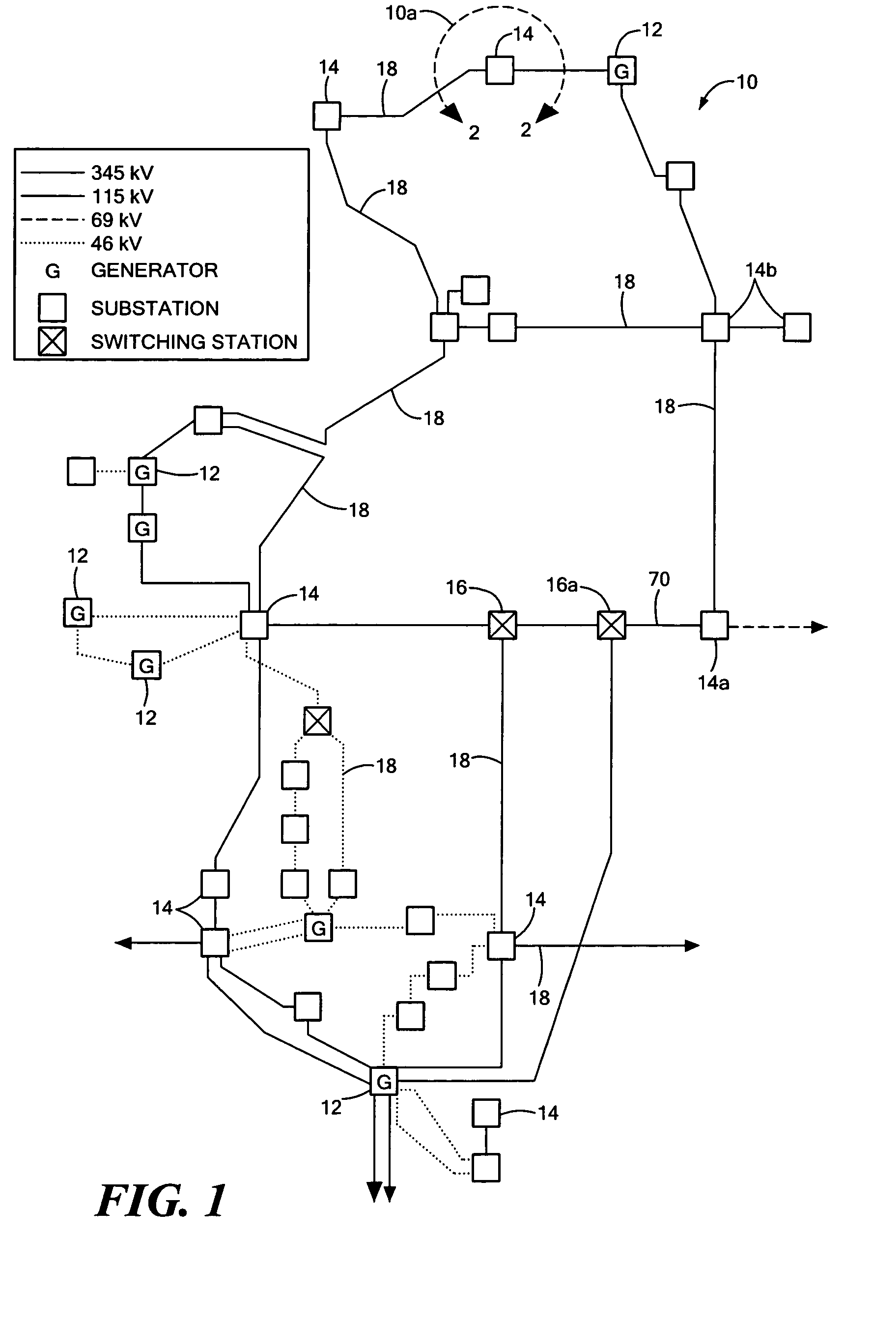
[0039]Referring to FIG. 1, a portion of a utility power network includes a transmission network 10 having generators 12, substations 14, and switching stations 16, all of which are interconnected via transmission lines 18. Transmission lines 18, in general, carry voltages in excess of 25 kilovolts (kV). With reference to FIG. 1, the transmission system voltages are indicated in the accompanying key located at the lower right.

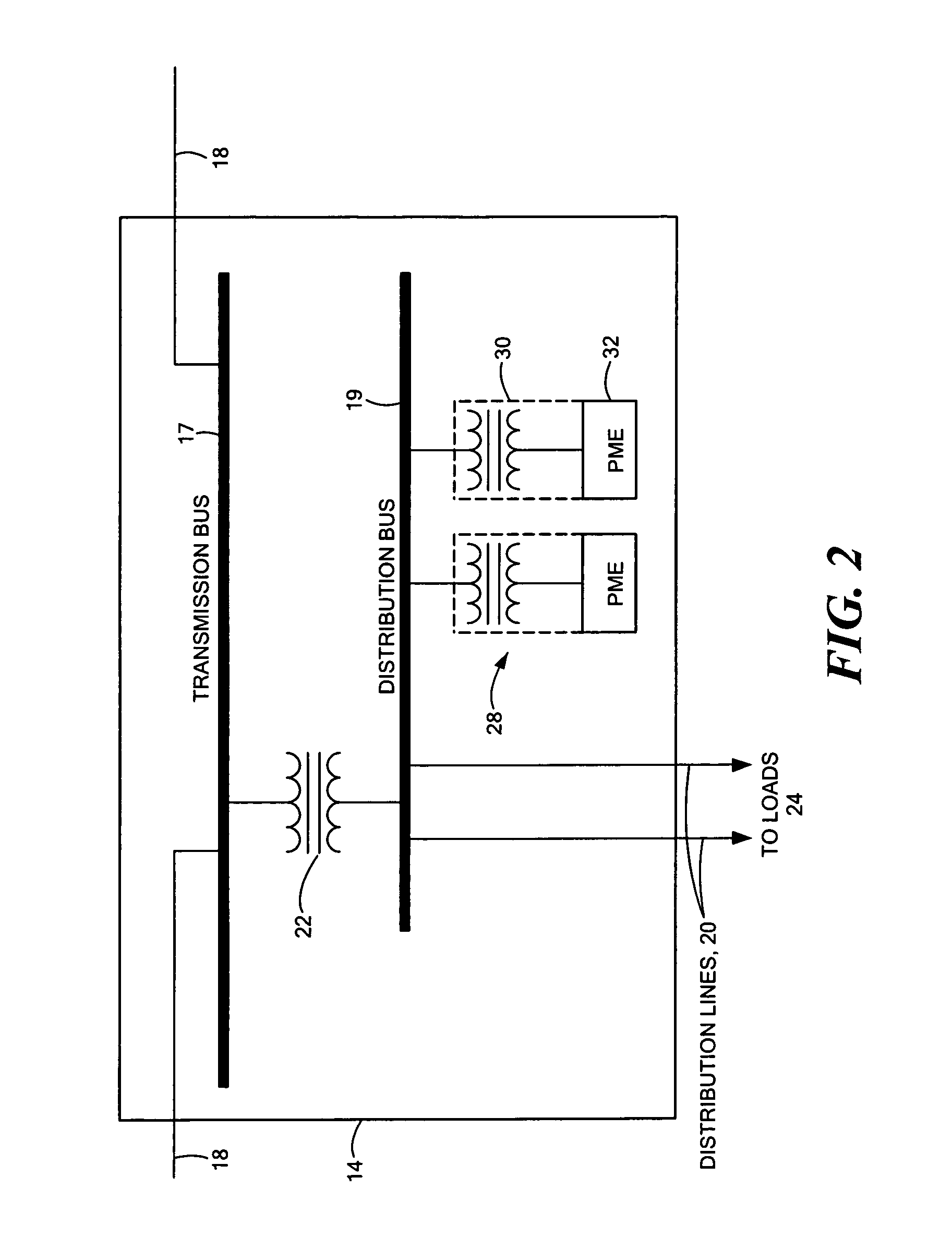
[0040]Referring to FIG. 2, an exploded portion 10a of the utility power network of FIG. 1, includes transmission lines 18 connected through circuit breakers (not shown) to a transmission bus 17 within the substation 14. A step-down transformer 22 connects the transmission bus 17 to a distribution bus 19 which is further connected to distribution lines 20 that carry power to loads 24 at voltage levels less than those levels associated with transmission lines 18 (e.g., 25 kV or less).

[0041]Reactive power compensation systems 28 are coupled to the distribution bus ...


PUM

PropertyMeasurementUnit
carrying voltagesaaaaaaaaaa
temperatureaaaaaaaaaa

Abstract

A reactive power compensation system includes a reactive power compensation device and a transformer electrically connected to the reactive power compensation device and having a cooling unit. The reactive power compensation device has an enclosure housing power electronics and at least one fan which provides an airflow for cooling the power electronics. The enclosure further includes an air outlet through which the airflow exits the enclosure after cooling the power electronics. The air outlet and the airflow are directed toward the cooling unit of the transformer to provide supplementary cooling to the transformer. The transformer cooling unit comprises external cooling fins in a liquid-filled transformer embodiment and comprises an air inlet of the transformer housing in a dry-type transformer embodiment. An optional duct may be provided between the enclosure and the transformer cooling unit.

Description

CROSS REFERENCE TO RELATED APPLICATIONS[0001]Not Applicable.STATEMENT REGARDING FEDERALLY SPONSORED RESEARCH[0002]Not Applicable.FIELD OF THE INVENTION[0003]This invention relates generally to cooling for a reactive power compensation system and, more particularly, to cooling the transformer of a reactive power compensation system.BACKGROUND OF THE INVENTION[0004]To remain competitive, electrical utility companies continually strive to improve system operation and reliability while reducing costs. To meet these challenges, the utility companies are developing techniques for increasing the life of installed equipment, as well as diagnosing and monitoring their utility networks. Developing these techniques is becoming increasingly important as the size and demands made on the utility power grid continue to increase. A utility power grid is generally considered to include both transmission line and distribution line networks for carrying voltages greater than and less than about 25 kV,...

Claims


Application Information

Patent Timeline
Patent Type & Authority Patents(United States)
IPC IPC(8): H01F27/08
CPCH01F27/085H01F27/025
Inventor FOLTS, DOUGLAS C.BOWERS, GARY J.
Owner AMERICAN SUPERCONDUCTOR
Why Eureka
Try Eureka