
Self-adjusting voltage filtering technique compensating for dynamic errors of capacitive voltage transformers

a capacitive voltage transformer and dynamic error technology, applied in the field of digital measurement of voltage signals, can solve the problems of affecting the stability of the entire power system, and requiring less cvts

Active Publication Date: 2009-07-28
GENERAL ELECTRIC CO
View PDF8 Cites 4 Cited by
  • Summary
  • Abstract
  • Description
  • Claims
  • Application Information

AI Technical Summary

Problems solved by technology

A failure often takes the form of an insulation breakdown, (fault) and results in a change in a system voltage and / or current.
Further, the longer a fault persists in the power system, the greater the likelihood that the stability of the entire power system will be compromised.
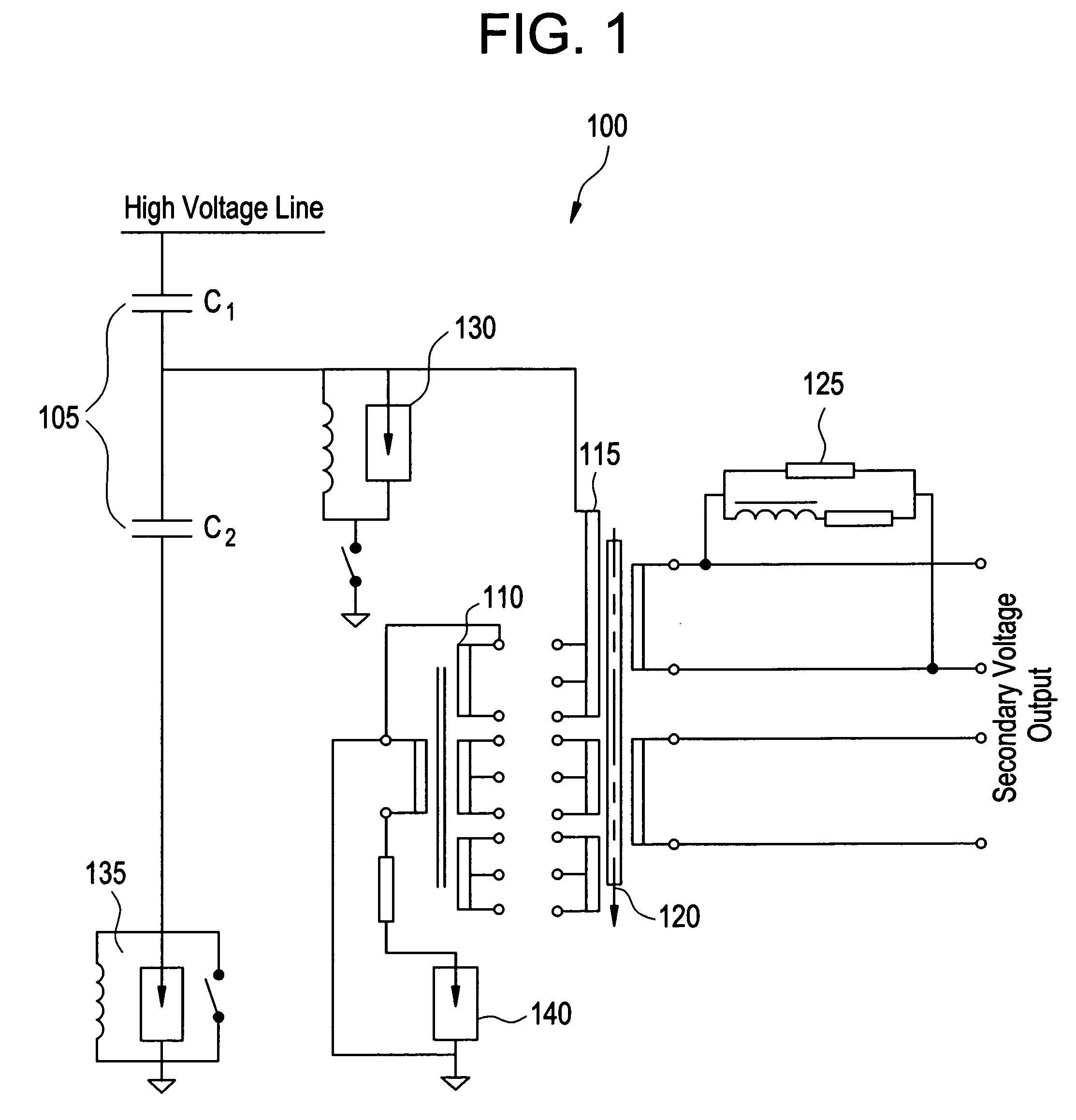
Typically, CVTs are cheaper than magnetic voltage transformers but create problems for protective relays since they have a tendency to add specific transients to the voltage signals as they are transformed to the secondary level.
This will impact the fault identification performance of the relay.

Method used


Image

  • Self-adjusting voltage filtering technique compensating for dynamic errors of capacitive voltage transformers
  • Self-adjusting voltage filtering technique compensating for dynamic errors of capacitive voltage transformers
  • Self-adjusting voltage filtering technique compensating for dynamic errors of capacitive voltage transformers

Examples


Embodiment Construction

[0027]One or more exemplary embodiments of the invention are described below in detail. The disclosed embodiments are intended to be illustrative only since numerous modifications and variations therein will be apparent to those of ordinary skill in the art.

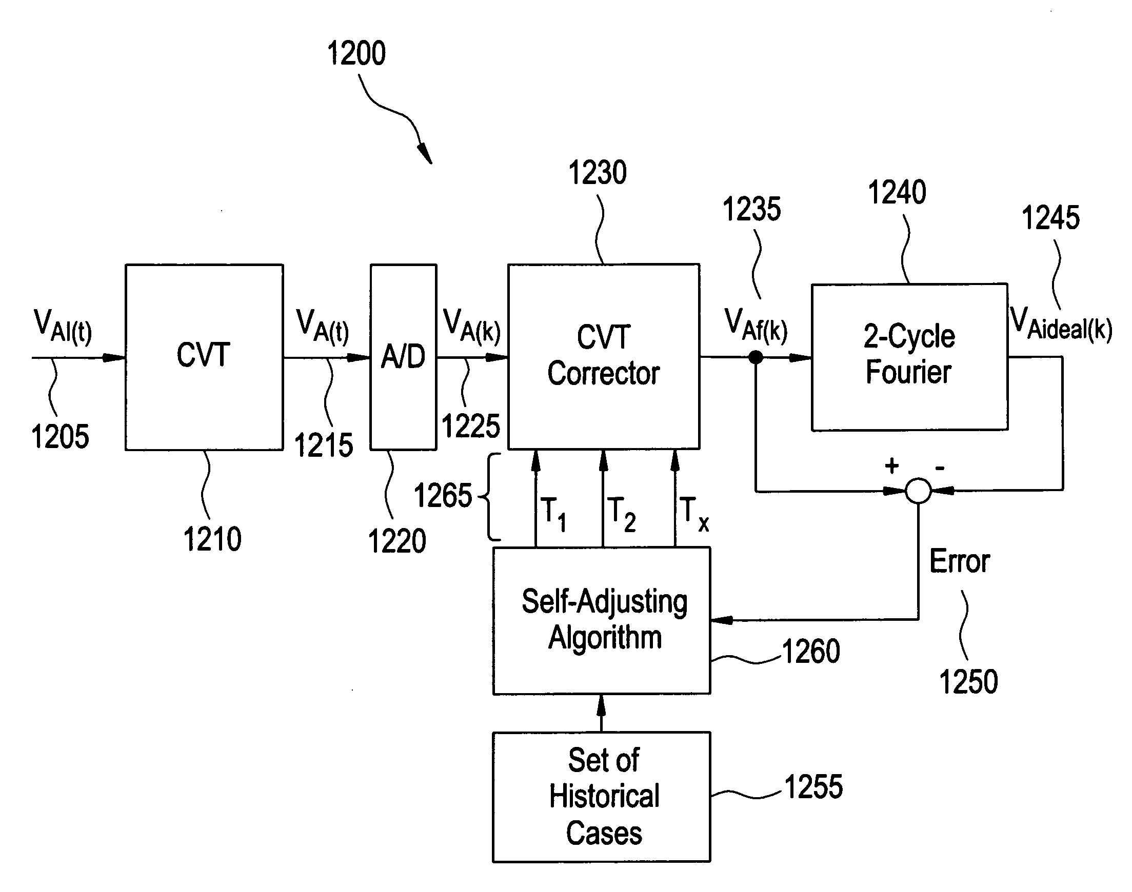
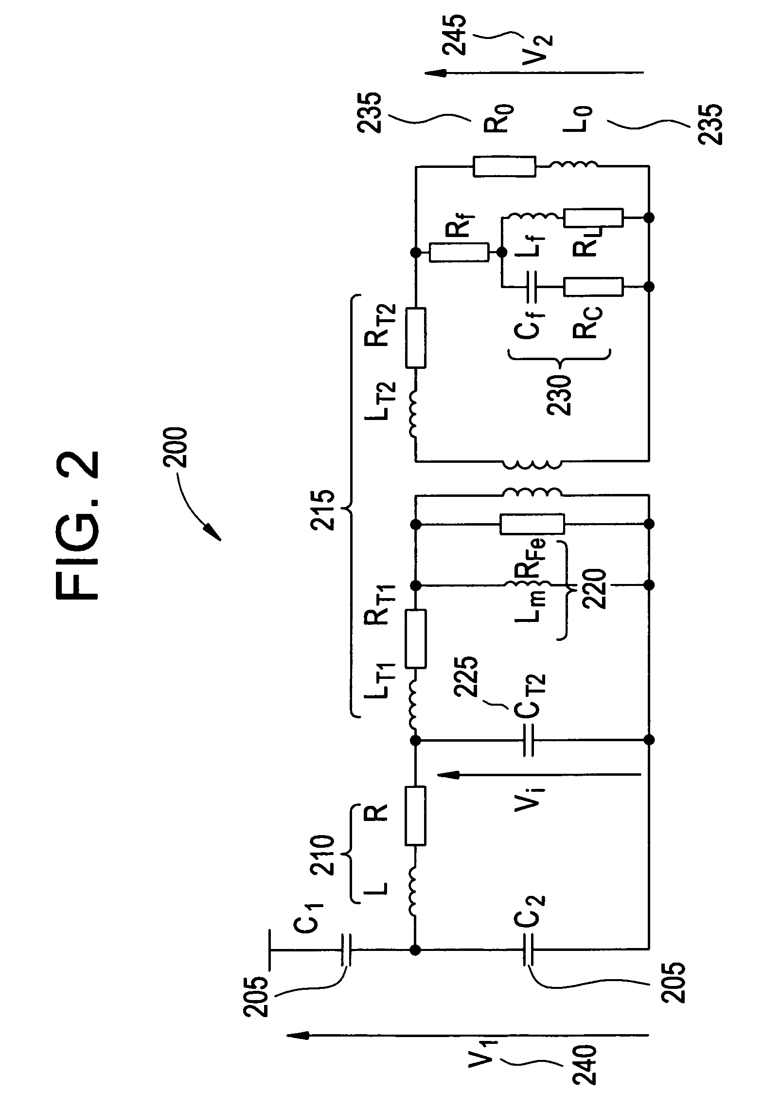
[0028]Aspects of the present invention utilize common design and operation principles of a typical CVT to simplify the equivalent circuit diagram of the CVT to a three-parameter model. This means that the dynamic behavior of the CVT, including the significant transient components during fault conditions affecting response of protective relays, are characterized by three parameter model. Further, the three parameters are expressed as time constant.

[0029]Within further aspects of the present invention a digital infinite impulse Response (IIR) filter is designed to process the raw output from the CVT with the purpose to re-create the best possible replica of the true voltage signal measured by the CVT. The IIR filter is designed bas...


PUM


Abstract

A method of digitally correcting the raw output voltage from a Capacitive Voltage Transformer (CVT) with the intent to remove transient components impacting on transient accuracy of protection function. A typical CVT is represented using three parameters in the linear CVT model. A digital filter designed based on the three parameters and incorporating a dedicated mechanism to ensure numerical stability of the former. A method of self-adjusting the said filter based on system events and performed after the method has been deployed in the field and supplied from a specific CVT.

Description

BACKGROUND OF THE INVENTION[0001]1. Field of the Invention[0002]The present invention relates to the digital measurement of voltage signals for protective relaying purposes in situations where the voltage is derived from, a capacitive voltage transformer (CVT), and particularly to improving the dynamic accuracy of protective functions that are dependant on voltage measurement.[0003]2. Description of Background[0004]Protective relays are devices that are designed to identify and isolate failures in a power system. A failure often takes the form of an insulation breakdown, (fault) and results in a change in a system voltage and / or current. Typically, within a power system, protective relays are configured to detect failures of a specific portion of the power system, theses specific portions of the power system being commonly referred to as zone. A protective relay guarding against short circuits should never respond to events other than failures within its particular zone. Further, th...

Claims


Application Information

Patent Timeline
Patent Type & Authority Patents(United States)
IPC IPC(8): G01R35/00
CPCH03H17/04G01R15/16H03H2017/0477G01R15/06H02H7/04G01R15/00H02H3/24
Inventor KASZTENNY, BOGDAN Z.PREMERLANI, WILLIAM JAMESRADUCANU, IULIAN
Owner GENERAL ELECTRIC CO
Learn More