Burner ignition and control system

a technology of control system and burner, applied in the direction of combustion process, combustion regulation, fuel supply regulation, etc., can solve problems such as system shutdown, and achieve the effect of reducing the requirement for energy consumption

Inactive Publication Date: 2009-08-04
CELERITY ENERGY SERVICES
View PDF19 Cites 21 Cited by
  • Summary
  • Abstract
  • Description
  • Claims
  • Application Information

AI Technical Summary

Benefits of technology

[0009]In accordance with embodiments of the present invention, a control system is taught which minimizes a requirement for energy consumption by implementing a timer or watchdog system into a control system which requires minimal power to periodically interrogate a state of a device being controlled. When the control system senses an operational state, it returns to sleep. When the control system senses a non-operational state, it momentarily utilizes energy to trigger one or more latches to change state, causing the device to be made operational and then returns to sleep. Additionally, should the device not be made operational as a result of the activation of the latch, further sensing of a non-operational state would cause the system to be shut down by momentarily energizing the latch.
[0011]More particularly, in one embodiment, a long-life energy source such as a lithium battery is utilized as the power source to switch the latching valves. To minimize the current drain from the battery, all of the circuits including the control valves remain un-energized except for the brief time required to change the state of the latching valves. As the current drain from the battery is required only to change the state of the latching valves and is not required to maintain the latch once it has been switched, the battery life is extended resulting in less frequent replacement or recharging.

Problems solved by technology

Additionally, should the device not be made operational as a result of the activation of the latch, further sensing of a non-operational state would cause the system to be shut down by momentarily energizing the latch.

Method used


Image

  • Burner ignition and control system
  • Burner ignition and control system
  • Burner ignition and control system

Examples


Embodiment Construction

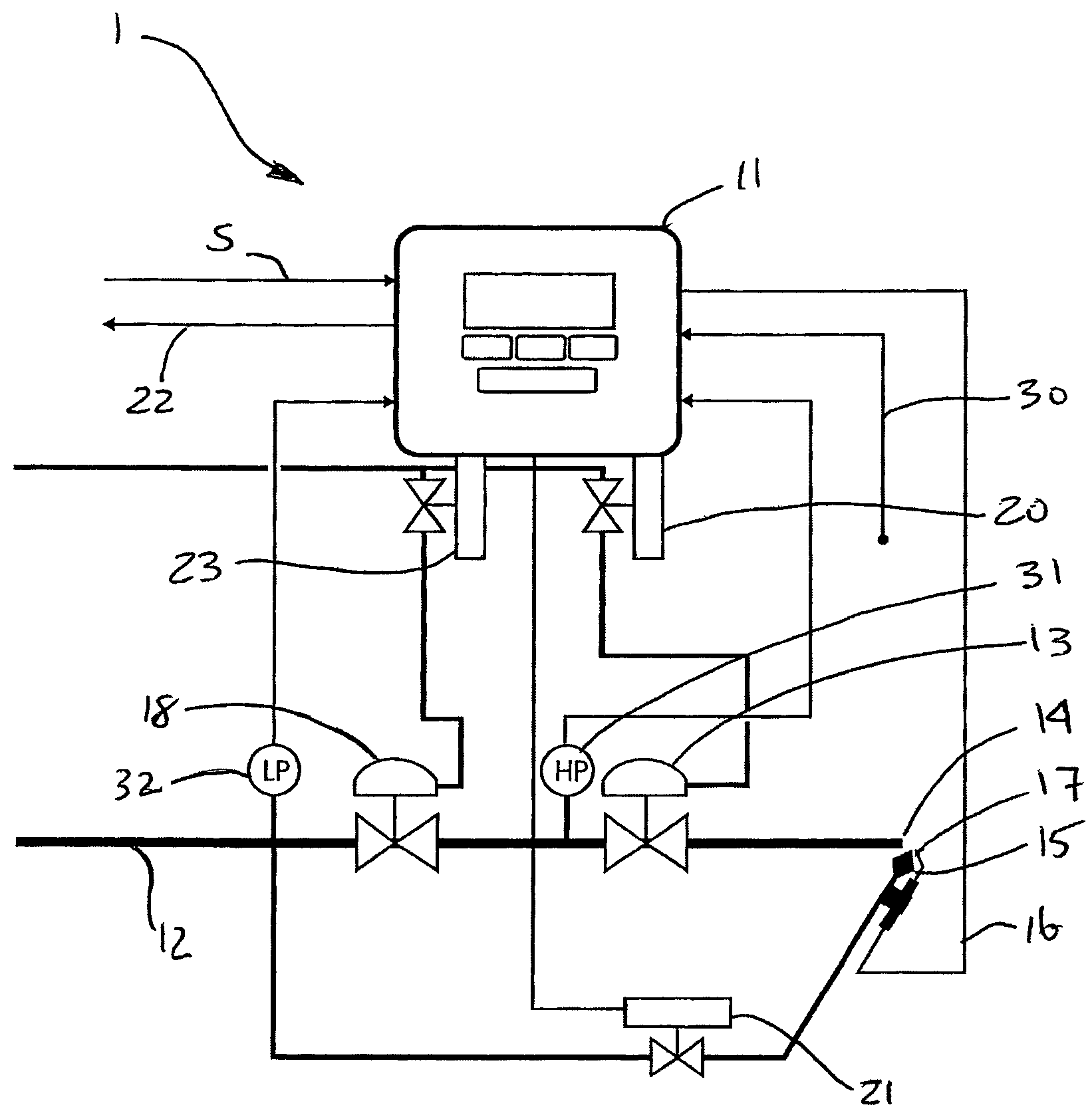
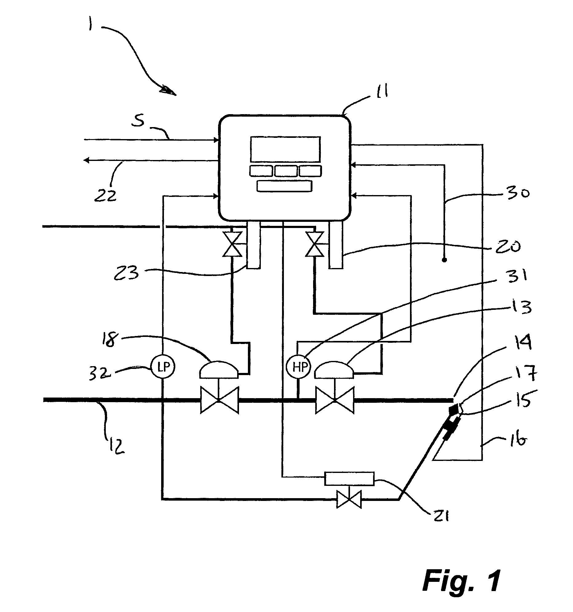
[0017]Embodiments of the invention utilize at least one latch which is operable between an open state and a closed state and which utilizes minimal power to switch between states and virtually no power therebetween. Further, power is not required to maintain the latch in either state once switched. Minimum power usage is achieved by a timer which actuates a sequence of events to determine the operation or state of an apparatus at period intervals. When the apparatus is detected to be in a first state, the latch is maintained in the open state, without the need to apply power to maintain it in that state. If the apparatus is determined to be in a second state, the latch is switched to the closed state. Each time the latch or latches are switched only a momentary application of power operable only for switching between states is required, thus power is conserved.

[0018]Having reference to FIG. 1, a burner control system 10 embodiment is shown. The system 1 comprises a controller 11 whi...


PUM


Abstract

A battery powered ignition and control system for a gas burner includes circuits for controlling a pilot burner, a main burner, a flame sensor and an igniter. Mechanically latched valves, which require power only to switch between and open and closed state are used to control the pilot and main gas. The circuitry spends a majority of time in a powered down state and draws power only when required to interrogate the state of the flame and to perform an ignition sequence as required, as periodically dictated by a watchdog system. The latching valves are electrically pulsed to change state and thus draw very low average power when called upon. Lithium batteries provide system power for a long duration.

Description

CROSS REFERENCE TO RELATED APPLICATION[0001]This application claims priority of U.S. provisional application Ser. No. 60 / 525,881, filed Dec. 1, 2003, the entirety of which is incorporated herein by reference.FIELD OF INVENTION[0002]Embodiments of the invention relate to gas burner controls for gas heaters and the like, and in particular to a new and novel way to power and control said burner such that the system draws very low average electrical power.BACKGROUND OF THE INVENTION[0003]A specialized type of heater apparatus is conventionally used for heating natural gas pipelines. The requirement for such heaters arises as a result of the possibility for condensation of water and hydrocarbon vapors, entrained in the natural gas, which can produce hydrates and resulting problems therefrom. The problem is conventionally avoided by heating the pipeline gas through the use of the specialized pipeline heater.[0004]The need for pipeline heaters typically arises in locations along the pipeli...

Claims


Application Information

Patent Timeline
Patent Type & Authority Patents(United States)
IPC IPC(8): F23N5/00F23N1/00F23N5/20F23N5/24F23N5/26F23Q9/14
CPCF23N5/00F23N5/265F23N2023/22F23N2027/02F23N2023/08F23N2027/18F23N2223/08F23N2223/22F23N2227/02F23N2227/18
Inventor MACNUTT, ROBGUNTHORPE, GARY
Owner CELERITY ENERGY SERVICES
Why Eureka
Try Eureka