Translinear variable gain amplifier

a variable gain amplifier and translinear technology, applied in differential amplifiers, amplifiers with semiconductor devices/discharge tubes, power conversion systems, etc., can solve the problems of reducing system capacity, high bias current in vga and other circuits, unwanted attributes of portable devices, etc., to achieve wide control range, facilitate broadband operation, and cascade easily

Inactive Publication Date: 2005-05-12
III HLDG 6
View PDF14 Cites 19 Cited by
  • Summary
  • Abstract
  • Description
  • Claims
  • Application Information

AI Technical Summary

Benefits of technology

[0006] The present invention includes a translinear variable-gain amplifier with adjustable gain and linearity. The amplifier operates over a wide control range, cascades easily, and allows broadband operation, while adding little distortion and consuming minimal power.

Problems solved by technology

This is important because distortion produced by the receiver VGA limits its ability to reject interfering signals, while distortion produced by the transmitter VGA spills power into adjacent communication channels and thereby reduces system capacity.
To minimize distortion, the bias current in the VGA and other circuits is typically high—an unwanted attribute for portable devices.

Method used


Image

  • Translinear variable gain amplifier
  • Translinear variable gain amplifier
  • Translinear variable gain amplifier

Examples


Embodiment Construction

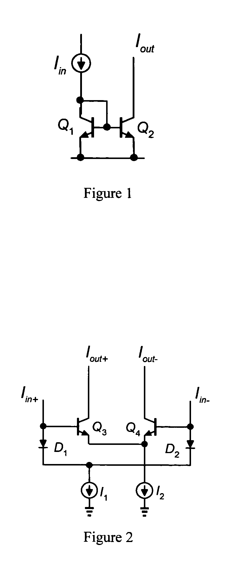
[0017]FIG. 1 shows a current mirror circuit that utilizes the translinear principle. In this circuit, the input current Iin flows through transistor Q1 and develops a base-emitter voltage (VBE1) given by VBE⁢ ⁢1=VT⁢ln⁡(IinIS⁢ ⁢1)

where VT is the thermal voltage and IS1 is the saturation current of transistor Q1. The base-emitter voltage of transistor Q1 is impressed upon or “mirrored” to the base-emitter junction of transistor Q2, producing an output current Iout equal to: Iout=IS⁢ ⁢2⁢exp⁡(VBE⁢ ⁢2VT)

Rearranging these equations yields the following translinear relationship:

JQ1=JQ2

where the current densities (J) of the transistors are JQ⁢ ⁢1=IinAe⁡(Q⁢ ⁢1)⁢ ⁢and⁢ ⁢JQ⁢ ⁢2=IoutAe⁡(Q⁢ ⁢2),

with

the emitter area (Ae) of each transistor proportional to the saturation current (IS).

[0018]FIG. 2 shows a current gain cell that also utilizes the translinear principle. In this circuit, the input currents Iin+ and Iin− develop the following diode voltages: VD⁢ ⁢1=VT⁢ln⁡(Iin+IS)⁢ ⁢VD⁢ ⁢2=...


PUM


Abstract

A translinear variable-gain amplifier. The translinear variable gain amplifier receives a differential input voltage and produces a differential output current having a selected gain. The amplifier comprises a buffer amplifier that receives the differential input voltage and produces a differential input current. The amplifier further comprises a translinear gain cell coupled to receive the differential input current and produce the differential output current. The gain cell includes a first adjustable bias source that operates to set a linear input range of the gain cell, and a second adjustable bias source that operates to set a gain value of the gain cell.

Description

CROSS REFERENCE TO RELATED APPLICATIONS [0001] This Application is a Continuation of U.S. patent application Ser. No. 10 / 229,327 filed on Aug. 27, 2002. The application Ser. No. 10 / 229,327 claims the benefit of priority from a U.S. Provisional Patent Application entitled “TRANSLINEAR VARIABLE GAIN AMPLIFIER” Ser. No. 60 / 316,768 filed on Aug. 31, 2001, the disclosure of which is incorporated by reference herein in its entirety for all purposes.FIELD OF THE INVENTION [0002] The present invention relates generally to variable-gain amplifiers, and more specifically, to a translinear variable-gain amplifier. BACKGROUND OF THE INVENTION [0003] The signals received and transmitted in wireless communications systems often vary in strength and thus require the use of variable gain amplifiers in the radio transceiver. These variable gain amplifiers operate to remove fluctuations in the received signal and to compensate for path losses in the transmitted signal. [0004] Ideally, the variable ga...

Claims


Application Information

Patent Timeline
Patent Type & Authority Applications(United States)
IPC IPC(8): H03F3/45
CPCH03F2203/45612H03F3/45085
Inventor GROE, JOHN B.FARIAS, MICHAEL
Owner III HLDG 6
Why Eureka
Try Eureka