Active clamping for zero current zero voltage forward conversion

a forward converter and clamping technology, applied in the direction of electric variable regulation, process and machine control, instruments, etc., can solve the problems of capacitors having a larger external shape, limited maximum duty factor dmax, conductance loss, etc., to reduce the size of the capacitor, reduce the loss of the switching element, and reduce the withstand voltage

Inactive Publication Date: 2002-05-28
NEC CORP
View PDF15 Cites 14 Cited by
  • Summary
  • Abstract
  • Description
  • Claims
  • Application Information

AI Technical Summary

Benefits of technology

is to improve on these problems by providing an active clamp forward converter that reduces the maximum voltage applied to a switching element as well as the charging voltage of a capacitor, and allows the use of the switching element and a capacitor having lower withstand voltages, resulting in low on loss of the switching element and enabling the size of the capacitor to be made smaller as well as a wide control range for the on duty factor.

Problems solved by technology

Consequently, the problem was encountered in which the maximum on duty factor Dmax ends up being restricted by the withstand voltage of the switching element or capacitor.
Consequently, there was the problem of the conductance loss when the switching element 2 is on conversely increasing.
In addition, there was also the problem with respect to capacitor 9 in which, as the rated voltage becomes higher, the capacitor having a larger external shape is required.

Method used


Image

  • Active clamping for zero current zero voltage forward conversion
  • Active clamping for zero current zero voltage forward conversion
  • Active clamping for zero current zero voltage forward conversion

Examples


Embodiment Construction

The following provides an explanation of the embodiments of the present invention with reference to the drawings.

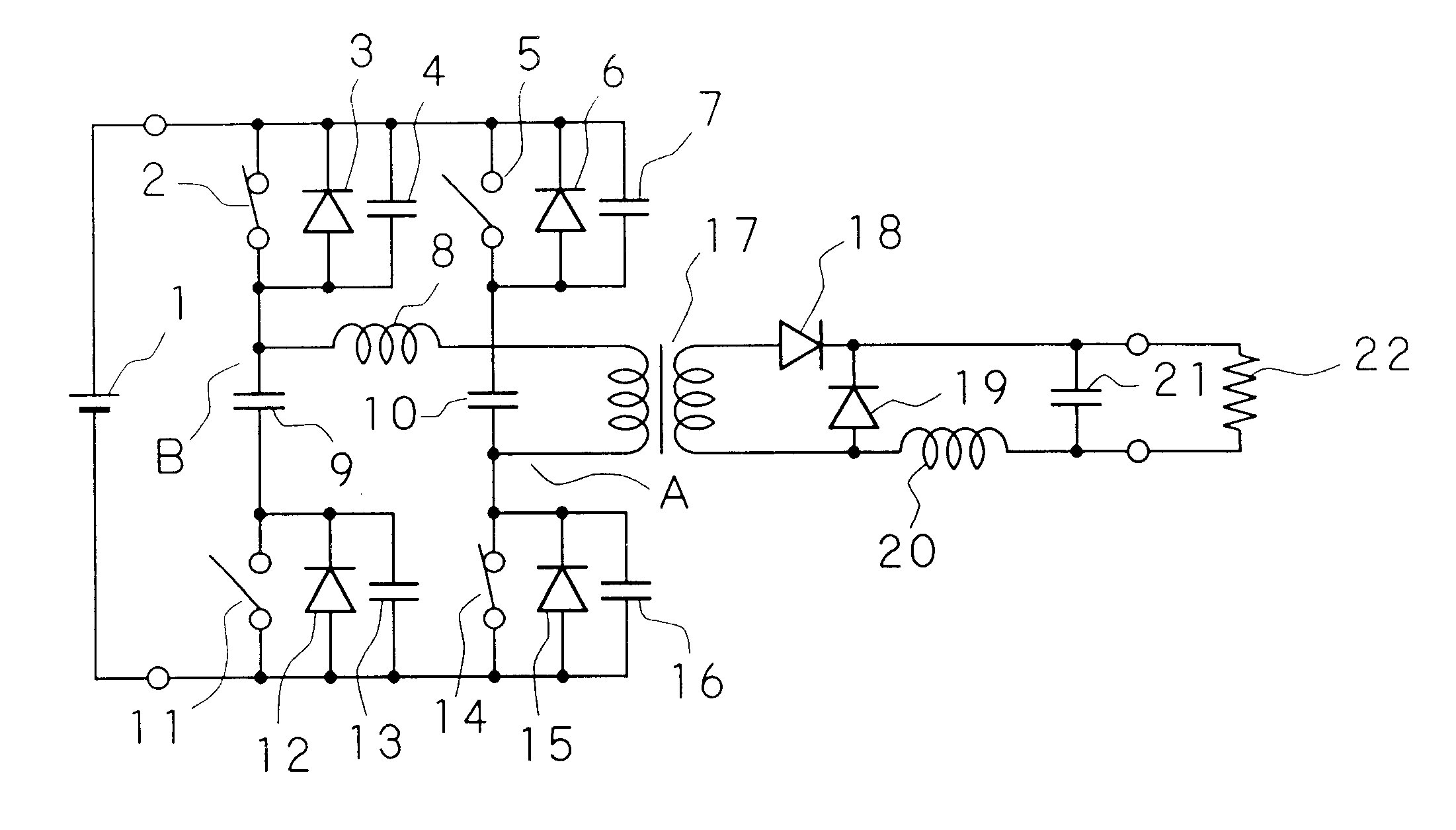
FIG. 1 is a circuit drawing showing the example of a constitution of an active clamp forward converter concerning a first embodiment of the present invention.

The active clamp forward converter is equipped with: a transformer 17 in which one end of the primary coil is connected to a contact A, an inductor 8 connected between the other end of the primary coil of the transformer 17 and a contact B, a switching element 2 connected between the positive terminal of a direct current power supply 1 and the contact B, a switching element 14 connected between the contact A and the negative terminal of the direct current power supply 1, a switching element 5 and a capacitor 10 connected in series between the positive terminal of the direct current power supply 1 and the contact A, a capacitor 9 and a switching element 11 connected in series between the contact B and the negative ter...


PUM


Abstract

The present invention discloses an active clamp forward converter that reduces the charging voltage of clamp capacitors as well as the voltage applied to switching elements, making it possible to reduce the on loss of the switching elements while also enabling the size of the capacitance elements to be reduced. The active clamp forward converter comprises first and second FETs which respectively connects first and second ends of a primary coil of the transformer to positive and negative terminals of a direct current power supply, and third and fourth FETs which respectively connects the first and second ends to the negative and positive terminals of a direct current power supply via capacitors, wherein the pair of first and second FETs and the pair of third and fourth FETs are alternately switched on and off sandwiched about a period when both are off.

Description

1. Field of the InventionThe present invention relates to an active clamp forward converter, and more particularly, to an active clamp forward filter having low levels of switching loss and conductance loss.2. Description of the Related ArtFIG. 9 is a circuit drawing showing an example of the prior art of a single-transistor, forward active clamp circuit disclosed in Japanese Unexamined Utility Model Application, First Publication No. 4-72882. This circuit is equipped with a transformer 17 in which a first end of a primary coil is connected to the positive terminal of a direct current power supply 1 via an inductor 8, and a second end of a primary coil is connected to the negative terminal of a direct current power supply 1 via a switching element 2.A capacitor 9 and a switching element 5 are additionally connected in series between the positive terminal of direct current power supply 1 and the second end of the primary coil of the transformer 17. In addition, a diode 3 and a capaci...

Claims


Application Information

Patent Timeline
Patent Type & Authority Patents(United States)
IPC IPC(8): H02M3/337H02M3/335H02M3/24H02M3/28H02M1/34
CPCH02M1/34H02M3/33592H02M3/337Y02B70/1491H02M2001/342Y02B70/1475H02M2001/0048Y02B70/10H02M1/0048H02M1/342H02M3/33573
Inventor KATO, TSUTOMU
Owner NEC CORP
Why Eureka
Try Eureka