Ceramic electronic component

Inactive Publication Date: 2002-09-19
MURATA MFG CO LTD
View PDF8 Cites 21 Cited by
  • Summary
  • Abstract
  • Description
  • Claims
  • Application Information

AI Technical Summary

Benefits of technology

[0009] Accordingly, an object of the present invention is to provide a low resistance ceramic electronic component having a high withstand voltage.
[0015] Known barium titanate semiconductive ceramics generally contain a sintering additive such as SiO.sub.2 and B.sub.2O.sub.3, whereas the semiconductive ceramic of the present invention does not contain any sintering additives. The ceramic of the present invention can exhibit a remarkable PTC by slight reoxidation after burning in reducing atmosphere. When a ceramic does not contain any sintering additives, the flux or the like in board level packaging lowers the withstand voltage of the ceramic. However, impregnating the ceramic with a glass component inhibits the withstand voltage from lowering.
[0016] By impregnating a ceramic having a relative density of about 90% or less, that is a ceramic containing no sintering additives, with a glass component, the ceramic electronic component of the present invention can exhibit a low resistance and a high withstand voltage.

Problems solved by technology

However, electrodes of a known laminated-ceramic electronic component have to use a base metal such as Ni to ensure ohmic contact, and therefor the component has to be burned in a reducing atmosphere.
Furthermore, the protective layer of the ceramic electronic component formed by coating an organic resin or an inorganic glass is deteriorated by heat generated by being applied in packaging or generated by surrounding electronic components after board level packaging.
Such a protective layer cannot be used for a long time even though the difference of the thermal expansion coefficients between the component and the protective layer thereof is small.

Method used


Image

  • Ceramic electronic component
  • Ceramic electronic component

Examples


example 2

[0026] A PTC thermistor 10 was prepared in the same process as Example 1 except for replacing the glass solution with a Li--Si--O glass solution, and then the resistance at room temperature and the withstand voltage were measured.

example 3

[0027] A PTC thermistor 10 was prepared in the same process as Example 1 except for replacing the glass solution with a K--Si--O glass solution, and then the resistance at room temperature and the withstand voltage were measured.

example 4

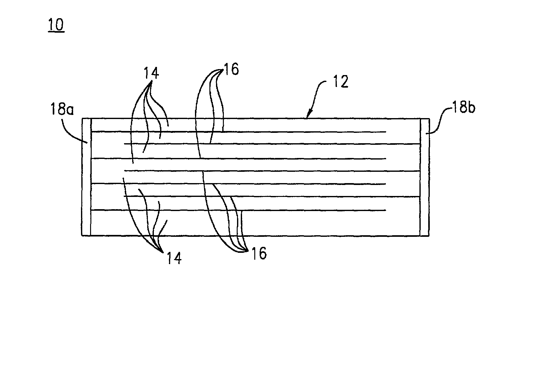
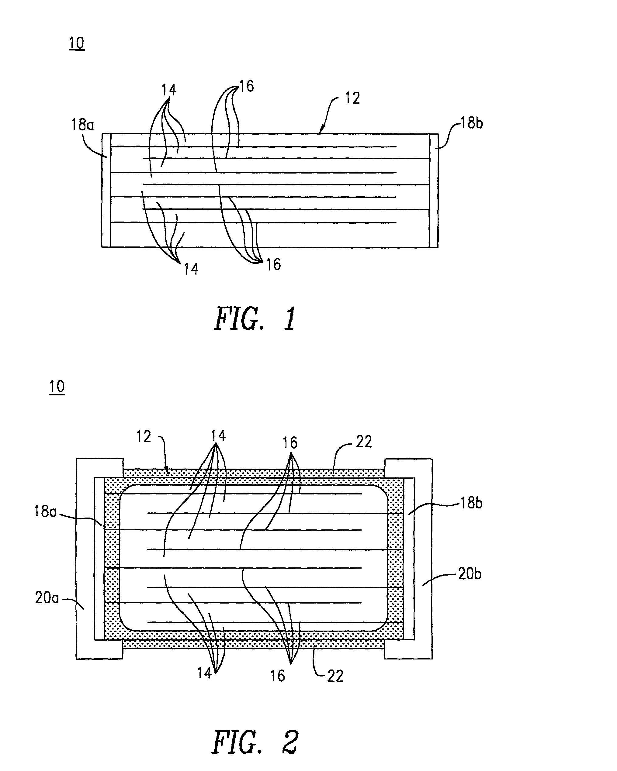
[0038] BaCO.sub.3, TiO.sub.2 and samarium nitric acid solution were used as starting materials for barium titanate semiconductive ceramics. These materials were weighed such that the molar ratio of Sm to Ti was 0.0012, and were mixed with zirconia balls for 5 hours in pure water. In the formulation, the ratio of Ba to Ti varied. Then the mixture was dried by evaporation and calcinated at 1150.degree. C. for 2 hours to be formed into a powder. The calcinated powder was mixed with a dispersant and pure water and was pulverized. A binder or the like was added to the powder to form a slurry. The slurry was molded into green sheets by the doctor blade method. Internal electrodes were screen-printed with Ni paste on the green sheets. The green sheets were stacked such that the internal electrodes were alternately exposed at one side of the stacked green sheets and the other side. Then the stacked sheets were press-bonded and cut, thereby resulting in a laminate. The top and bottom of the ...


PUM

PropertyMeasurementUnit
Fractionaaaaaaaaaa
Angleaaaaaaaaaa
Densityaaaaaaaaaa

Abstract

A ceramic electronic component includes a component body having semiconductive ceramic layers and internal electrodes. The semiconductive ceramic layers and the internal electrodes are alternately laminated. The semiconductive ceramic layers have a relative density of about 90% or less and contain no sintering additives. The component body is provided with an external electrode on each side thereof. The ceramic electronic component has a low resistance and a high withstand voltage.

Description

BACKGROUND OF THE INVENTION[0001] 1. Field of the Invention[0002] The present invention relates to a ceramic electronic component, and more specifically, an electric component for a positive temperature coefficient thermistor (PTC thermistor) and the like comprising a ceramic, such as a semiconductive ceramic mainly containing barium titanate.[0003] 2. Description of the Related Art[0004] Barium titanate semiconductive ceramics have been used for PTC thermistors which are generally used for the demagnetization of cathode-ray tubes, overcurrent protection, and other things. Lowering the resistance of the barium titanate semiconductive ceramics leads to a miniaturized and heavy-current ceramic electronic component, and accordingly, a laminated ceramic electronic component having inner electrodes has been developed.[0005] As technology has progressed, higher reliability for the ceramic electronic component has been demanded. In order to maintain moisture, heat or weather resistance of ...

Claims


Application Information

Patent Timeline
IPC IPC(8): C01G23/00C04B41/85C04B35/468C04B35/49H01C7/00H01C7/02H01C17/065H01L29/24
CPCC01G23/002C01G23/006C01P2006/40C04B35/4682H01C7/021H01C7/025H01C17/06533H01L29/24H01C7/00
Inventor KODAMA, MASAHIROKISHIMOTO, ATSUSHIKAWAMOTO, MITSUTOSHINIIMI, HIDEAKIANDO, AKIRA
Owner MURATA MFG CO LTD
Why Eureka
Try Eureka