Start-up circuit with high-tension power supply

A technology of starting circuit and high-voltage power supply, applied in the direction of electrical components, output power conversion devices, etc., can solve the problems of large space occupation, high cost, high input voltage, etc., achieve low raw material cost, reduce voltage stress, and improve reliability Effect

Active Publication Date: 2011-09-21
MORNSUN GUANGZHOU SCI & TECH
View PDF3 Cites 21 Cited by
  • Summary
  • Abstract
  • Description
  • Claims
  • Application Information

AI Technical Summary

Problems solved by technology

[0004] 1. If the input voltage range is large, in order to ensure normal startup at the lowest input voltage, the value of the power resistor R1 should not be too large, but this will increase the loss during high voltage input, affecting power conversion efficiency, heat dissipation and reliability. At the same time, high-power resistors must be selected, which occupy a large space and cost high;
[0005] 2. In order to reduce the loss, in the prior art, the resistor R1 is disconnected by adding peripheral circuits (such as figure 2 shown), but due to the high input voltage, it is difficult to find a device that can withstand high voltage on the market. Even if a high-voltage IGBT is available, its cost will be relatively high;
[0006] In order to make a switching power supply with small size, low cost and high conversion efficiency, it is very important to design a reliable and efficient start-up circuit. Therefore, the above-mentioned start-up circuit scheme is not suitable for high-voltage input applications.

Method used


Image

  • Start-up circuit with high-tension power supply
  • Start-up circuit with high-tension power supply
  • Start-up circuit with high-tension power supply

Examples


Embodiment Construction

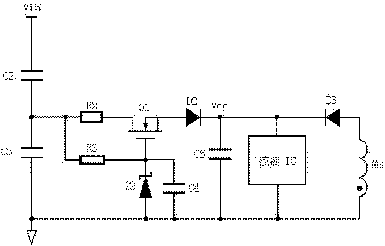
[0021] Such as image 3 As shown, the high-voltage power supply startup circuit described in Embodiment 1 of the present invention includes:

[0022] A capacitive voltage dividing circuit composed of the first voltage dividing capacitor C2 and the second voltage dividing capacitor C3 connected in series; the positive pole of the input voltage Vin is connected to one end of the first voltage dividing capacitor C2, and the other end of the first voltage dividing capacitor C2 is connected to the second voltage dividing capacitor C2. One end of the second voltage dividing capacitor C3 is connected to each other, and the other end of the second voltage dividing capacitor C3 is connected to the negative pole of the input voltage Vin.

[0023] The power resistor R3, capacitor C4 and Zener diode Z2 are connected to form a delay control loop; the cathode of the Zener diode Z2 is connected to the second voltage-dividing capacitor C3 and the upper-stage voltage-dividing capacitor (ie, th...


PUM


Abstract

The invention discloses a start-up circuit with a high-tension power supply, and the start-up circuit comprises a power resistor, an voltage-regulator diode, a current-limiting resistor, an MOS (metal oxide semiconductor field effect transistor) and a filter capacitor, wherein, the negative pole of the voltage-regulator diode is connected with the grid of the MOS, the positive pole of the voltage-regulator diode is connected with the negative pole of an input voltage, the grid of the MOS is connected with a drain through the power resistor and the current-limiting resistor, the source electrode of the MOS is connected with one end of the filter capacitor, the other end of the filter capacitor is connected with the negative pole of the input voltage, the two ends of the filter capacitor are the output ends of the start-up circuit, and the start-up circuit with the high-tension power supply also comprises a capacitor voltage division circuit which consists of at least two stages of voltage division capacitors connected in series; and the capacitor voltage circuit is connected between the positive pole and negative pole of the input voltage in parallel, one end of the last-stage voltage division capacitor is connected with the negative pole of the input voltage, the other end of the last-stage voltage division capacitor is connected with connections of the current-limiting resistor and the power resistor. The start-up circuit provided by the invention has advantages of less loss, high reliability and low cost.

Description

technical field [0001] The invention relates to a starting circuit of a switching power converter, in particular to a starting circuit of a switching power converter with a high voltage and a wide input range. Background technique [0002] In recent years, with the rapid development of power industries such as photovoltaic power generation and ultra-high voltage transmission, there is an increasing demand for switching power supplies. However, since the transmission voltage in the power transmission system is as high as thousands of volts or even higher, and the grid voltage fluctuation range is relatively large, and the photovoltaic battery is affected by the light intensity and load, the battery voltage fluctuation range is relatively large, and the development of the auxiliary power supply of the system is difficult. Greatly increased, especially the design of the high-voltage start-up circuit is very difficult. On the one hand, it is necessary to find electronic componen...

Claims


Application Information

Patent Timeline
Patent Type & Authority Applications(China)
IPC IPC(8): H02M1/36
Inventor 余凤兵周耀彬尹智群
Owner MORNSUN GUANGZHOU SCI & TECH
Why Eureka
Try Eureka