
Wireless communication apparatus

a communication apparatus and wireless technology, applied in pulse technique, phase-modulated carrier system, baseband system details, etc., can solve the problems of low power efficiency compared with saturation amplifier, deterioration of modulation accuracy and characteristics of spurious radiation to the outside of a communication channel band, and high linearity, so as to achieve high responsiveness, wide control range, and high responsiveness

Inactive Publication Date: 2007-02-27
HITACHI LTD
View PDF14 Cites 11 Cited by
  • Summary
  • Abstract
  • Description
  • Claims
  • Application Information

AI Technical Summary

Benefits of technology

[0010]In addition, the present invention provides a power supply voltage control circuit for the EER system with a wide control range and high responsiveness by combining an up-converter with a step-down element (regulator, etc.) with high responsiveness. The present invention also indicates a technique for analyzing transmission signal waveform information prior to output by a power amplifier to determine the necessity of switching of the systems or step-up and, at the same time, generating a control signal sent to each element.

Problems solved by technology

In the saturation region, since the form of the transmission signal is distorted largely, modulation accuracy and characteristics of spurious radiation to the outside of a communication channel band is deteriorated.
On the other hand, in a modulation system for transmitting information according to a change in only an amplitude or both of an amplitude and a phase (e.g., 16QAM: quadrature Amplitude Modulation), high linearity is required because data cannot be distinguished correctly on a reception side when a transmission signal is distorted.
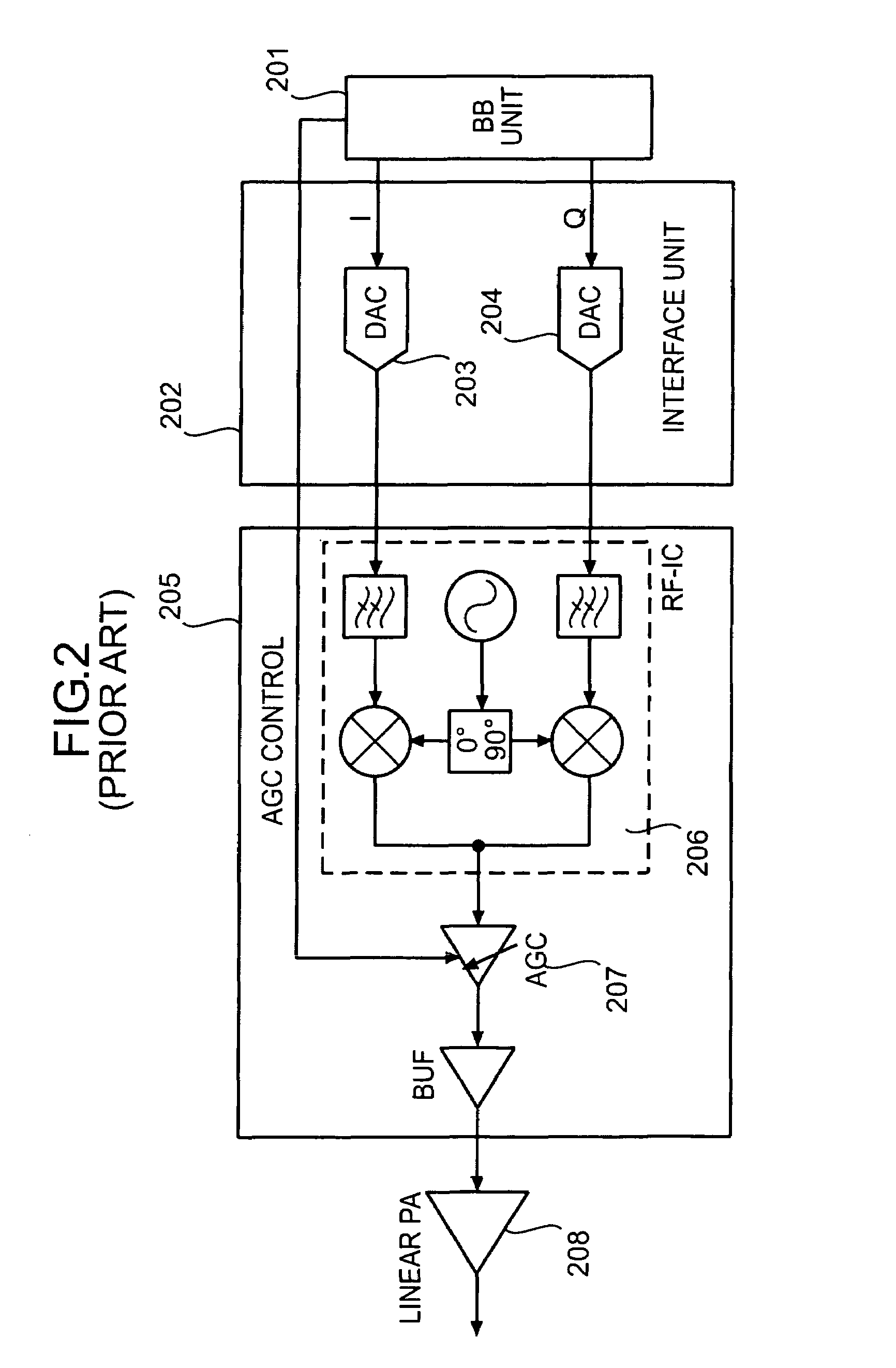
In this structure, since the linear amplifier is used, it is easy to satisfy linearity but a power efficiency is low compared with the saturation amplifier.
However, as it is also apparent from FIG. 7, an amplifier deviates from the saturation region in a range in which an output power is low, and efficiency is deteriorated.
In addition, since a dynamic range of an output power depends upon a variable range of a power supply voltage (range in which a change in an output power is proportional to a change in a power supply voltage), it is difficult to enlarge the range compared with the linear system in which a dynamic range is obtained by adjusting an input power.
Therefore, this system has been considered unsuitable for a wireless communication system in which an output power changes sharply over a wide range, that is, a modulation system with a large PAPR (Peak to Average Power ratio) of a signal is used or an average level of an output power changes over a wide range by transmission power control.
Thus, an increase in power consumption is a problem.

Method used


Image

  • Wireless communication apparatus
  • Wireless communication apparatus
  • Wireless communication apparatus

Examples


first embodiment

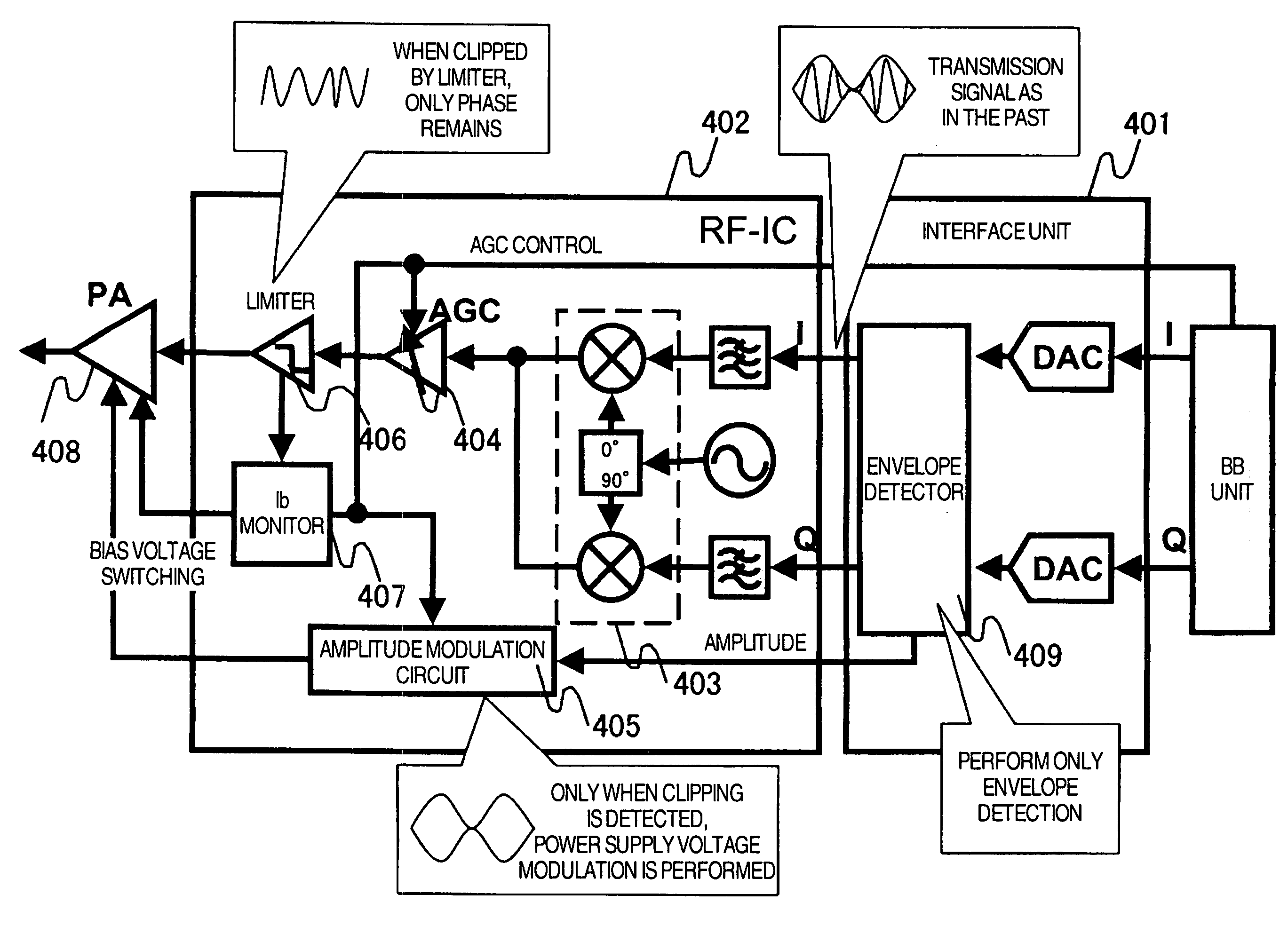
[0028]Next, with reference to FIG. 4, a structure of a transmission system wireless unit and an interface unit according to the present invention will be described. In this embodiment, only envelope detection (extraction of amplitude information) is performed rather than the Rθ conversion in an envelope detection section 409 of an interface unit 401, and an original transmission signal as IQ-separated and amplitude information are outputted to an RF-IC 402. The RF-IC 402 subjects the IQ-separated input signal to frequency conversion with an quadrature modulator 403 as in the past and amplifies the input signal in accordance with transmission power control with an AGC amplifier 404. Note that, although the quadrature modulator is used here, it is obvious that, even if a circuit structure is different, the same effect can be obtained if contents of processing are equivalent. A limiter 406 connected to a later stage of the AGC amplifier 404 clips an input signal of a fixed threshold vo...

second embodiment

[0029]Next, with reference to FIG. 5, the structure of the transmission system wireless unit and the interface unit according to the present invention will be described. In this embodiment, an Rθ conversion section 504 of an interface unit 502 is placed in front of DACs 505 and 506 to realizes its function according to digital signal processing. The Rθ conversion section 504 performs switching of the linear system / the EER system based upon transmission power level information from the base band unit 501. When the linear system is used, the Rθ conversion section 504 through-outputs a signal without performing signal processing. When the EER system is used, the Rθ conversion section 504 performs separation and extraction of amplitude information and phase information. The amplitude information is extracted by envelope detection as described earlier. Since the phase information is treated more easily in the RF-IC when it is represented by perpendicular two-component IQ, in this embodim...

fifth embodiment

[0032]Next, with reference to FIG. 14, the structure of the transmission system wireless unit and the interface unit according to the present invention will be described. In this embodiment, an offset PLL system as described in T. Yamawaki et al., “A 2.7-V GSM RF Transceiver IC” IEEE Journal of Solid-State Circuits, vol. 32, No. 12, pp 2089–2096, December 1997 is used in an RF-IC 1402.


PUM


Abstract

A linear system and an EER system are used in combination such that the EER system can also be used in a cellular phone with a wide output dynamic range. In the EER system, linear control of an amplifier becomes difficult in a low output range. Thus, use of the EER system is limited to a high output range, and the linear system is used in the low output range as in the past. A power efficiency is improved while requirements of linearity are satisfied by this structure. An effective circuit structure is proposed for a switching control system for two systems. In addition, an up-converter is constituted in combination with a step-down element with high responsiveness, whereby a power supply voltage control circuit for the EER system with a wide control range and high responsiveness is provided.

Description

BACKGROUND OF THE INVENTION[0001]The present invention relates to structures of an apparatus, which performs transmission in a wireless communication system such as a cellular phone or a wireless LAN, and an integrated circuit which is used as a component in the apparatus. In particular, the present invention relates to a wireless communication apparatus for a wireless communication system which adopts a modulation system for transmitting information according to changes in both of a phase and an amplitude.[0002]First, with reference to FIG. 7, a relation between input / output characteristics and a power efficiency of a power amplifier, which consumes largest electric power in a transmission apparatus for a wireless communication system and influences a power efficiency of the entire transmission apparatus, will be described (the figure is a schematic diagram and may not be always consistent with power efficiency characteristics of an individual power amplifier in some points). As it...

Claims


Application Information

Patent Timeline
Patent Type & Authority Patents(United States)
IPC IPC(8): H04K1/02H03F1/02H03F3/24
CPCH03F1/0205H03F1/0227H03F1/32H03F3/24H04L27/20H03F2200/102Y02B60/50H03F2200/451H03F2200/504H03F2200/66H04B2001/045H03F2200/324H03F1/02
Inventor SUZUKI, MAYTANAKA, SATOSHIYAMAWAKI, TAIZOTANOUE, TOMONORI
Owner HITACHI LTD
Learn More