Implantable sensing modules and methods of using

a sensing module and sensor technology, applied in the field of electromechanical devices, can solve the problems of insufficient environmental energy sources to power the sensor, impracticality, and need for batteryless operation, and achieve the effects of reducing the size of the sensor, prolonging the operation, and reducing the cost of operation

Inactive Publication Date: 2011-01-13
EVIGIA SYST
View PDF62 Cites 24 Cited by
  • Summary
  • Abstract
  • Description
  • Claims
  • Application Information

AI Technical Summary

Benefits of technology

[0011]In view of the above, it can be seen that an implantable sensing module according to the second aspect of the invention is well suited for implantation in a living body as a result of its size being minimized and its operation extended as a result of the electromechanical switches operating only during sensing events. As such, the implantable sensing module is capable of longer periods of operation compared to conventiona...

Problems solved by technology

Furthermore, in many applications a batteryless operation is needed due to lack of battery replacement feasibility, or to meet stringent cost, form factor, and lifetime requirements.
However, in many situations, these environmental energy sources are not adequately available to power a sensor.
Because of the size and complexity of many implantable sensing systems and the need for battery replacement to power the systems, individuals and the medical community have been reluctant to implant sensing systems into the human body.
In addition, a living body will reject and encapsulate an implanted system in a matter of days, often interfering with their operation and, in the case of chemical sensors, rendering them impractical.
There are many health problems that could benefit from real-time temperature monitoring, including determining overheating/heat stroke and/or hypothermia in athletes and other individuals.
The simplest form of temperature monitor is placed directly on the skin, though a drawback of this method is that the sensor will ...

Method used


Image

  • Implantable sensing modules and methods of using
  • Implantable sensing modules and methods of using
  • Implantable sensing modules and methods of using

Examples


Embodiment Construction

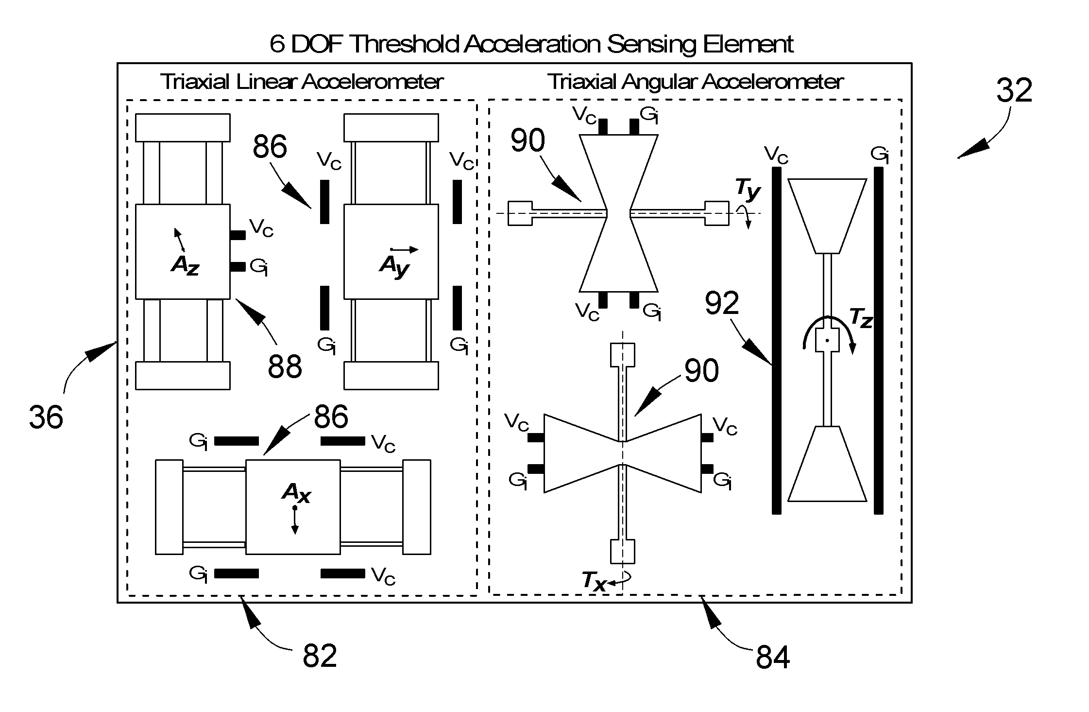
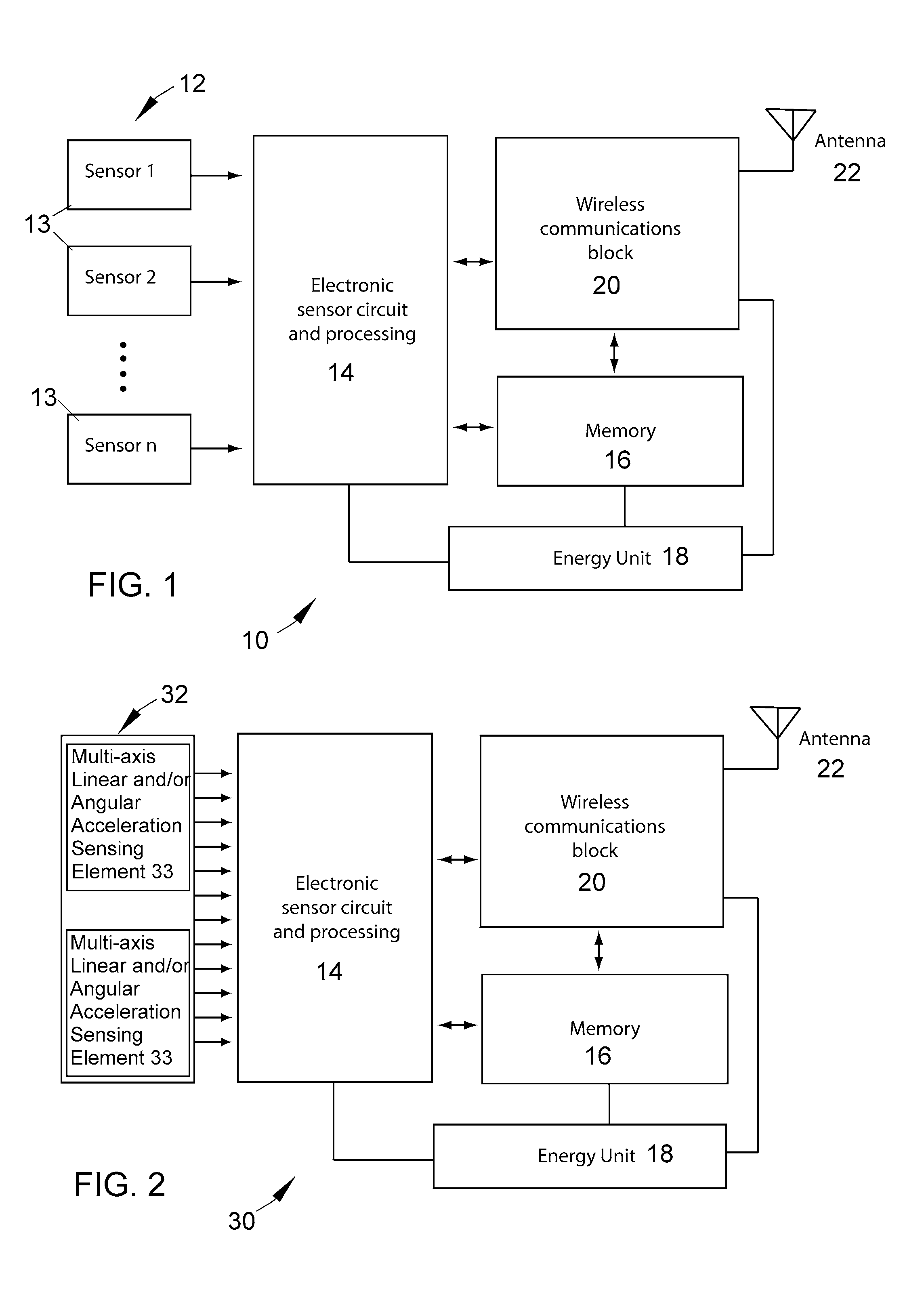
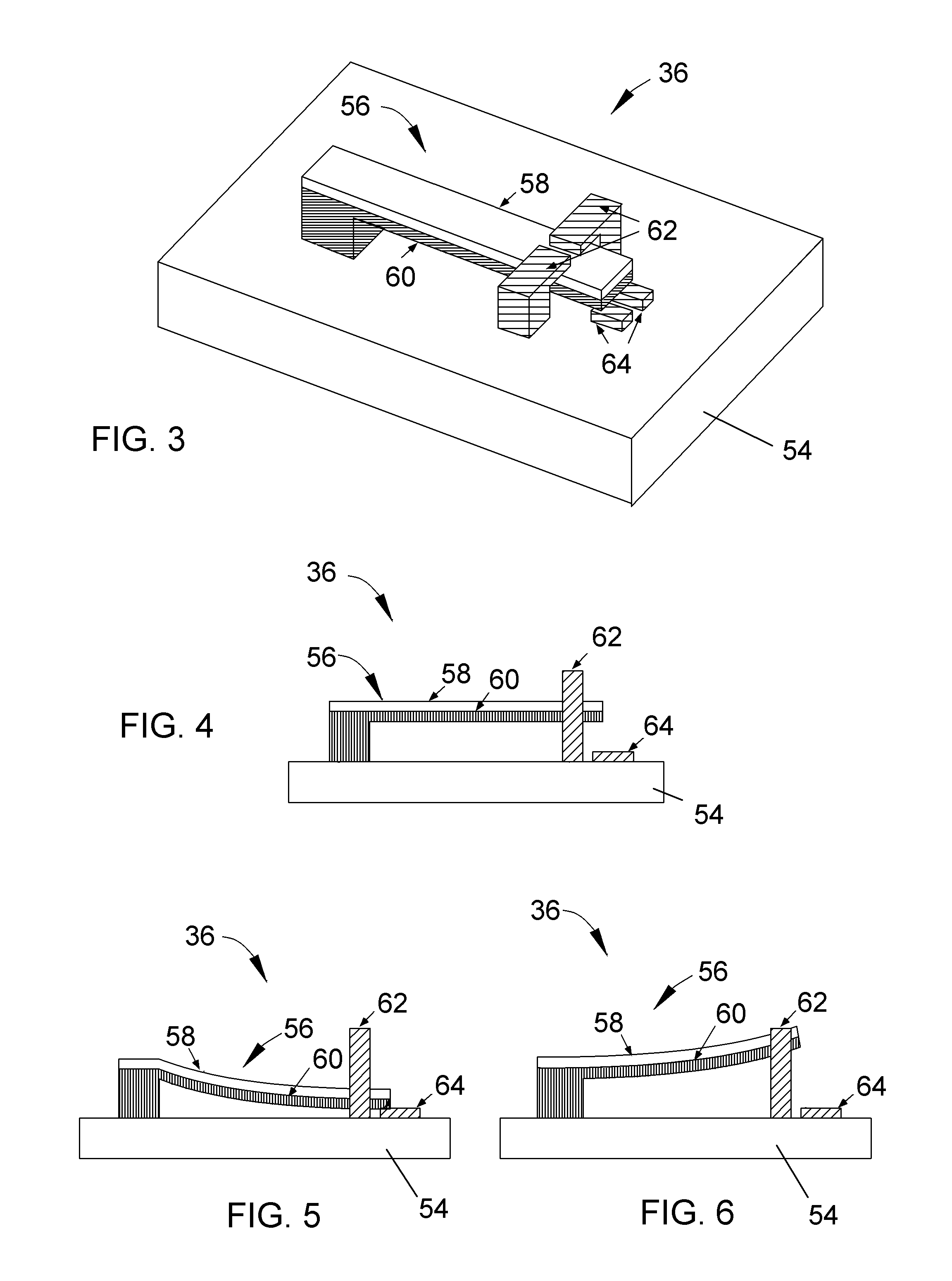
[0026]The present invention provides miniature implantable sensing modules whose small size enables the modules to be placed into a living body, preferably to a bone, tooth or other rigid surface where it can monitor and generate data relating to an external input, such as physiological parameters of the body and / or environmental parameters to which the body may be subjected. The modules make use of an energy storage device and one or more electromechanical sensing elements. The modules also preferably make use of non-volatile memory to store the data and a wireless communication system that enables the data to be retrieved from the modules by an external reader. The components of the modules are preferably selected so that the modules require very little power for their operation, enabling the modules to remain implanted and operable for long periods of time, potentially on the order of years, without need for replacement.

[0027]As will be evident from the following description, a p...


PUM


Abstract

Implantable sensing modules and methods for monitoring various physical parameters, including physical parameters of a living body and environmental parameters to which the living body may be subjected, for example, impacts. A method for monitoring impacts to which a living body is subjected entails the use of an implantable sensing module that has a rigid housing containing at least one energy storage device and at least one electromechanical sensing element that is responsive to impacts. The module generates data corresponding to impacts to which the electromechanical sensing element is subjected, and records the data in memory. The module is preferably implanted in a living body so that the module is connected to a rigid portion of the living body, in particular, a bone or tooth.

Description

CROSS REFERENCE TO RELATED APPLICATIONS[0001]This application claims the benefit of U.S. Provisional Application No. 61 / 272,066, filed Aug. 13, 2009, and is a continuation-in-part patent application of co-pending U.S. patent application Ser. No. 11 / 671,130, filed Feb. 5, 2007, which claimed the benefit of U.S. Provisional Application No. 60 / 765,244, filed Feb. 4, 2006. The contents of these prior applications are incorporated herein by reference.BACKGROUND OF THE INVENTION[0002]The present invention generally relates to electromechanical devices, such as micro-electromechanical systems (MEMS) and nano-electromechanical systems (NEMS). More particularly, this invention relates to implantable sensing modules capable of being implanted for the purpose of monitoring physical parameters of a living body and / or monitoring environmental parameters to which the body may be subjected, a particular but nonlimiting example of which is impacts sustained by the body.[0003]Wireless sensor systems...

Claims


Application Information

Patent Timeline
IPC IPC(8): A61B5/00
CPCG01D21/00G01K5/62G01P15/0888G01P15/135G01P15/18H01H1/0036G01P2015/0814H01H35/24H01H35/42H01H69/01H01H2001/0063H01H2037/008H01H2300/032H01H35/14
Inventor HOWER, ROBERT WILLIAMYAZDI, NAVIDZHANG, YAFAN
Owner EVIGIA SYST
Why Eureka
Try Eureka