
High voltage electricity transmission line monitoring method based on wireless communication and optical communication

A high-voltage transmission line, wireless communication technology, applied in wireless communication, circuit devices, data exchange through path configuration, etc., can solve the problems of inconvenient management and maintenance, high operation cost, low reliability, etc. High-quality, reliable results

Inactive Publication Date: 2009-07-15
NORTHWEST CHINA GRID
View PDF0 Cites 97 Cited by
  • Summary
  • Abstract
  • Description
  • Claims
  • Application Information

AI Technical Summary

Problems solved by technology

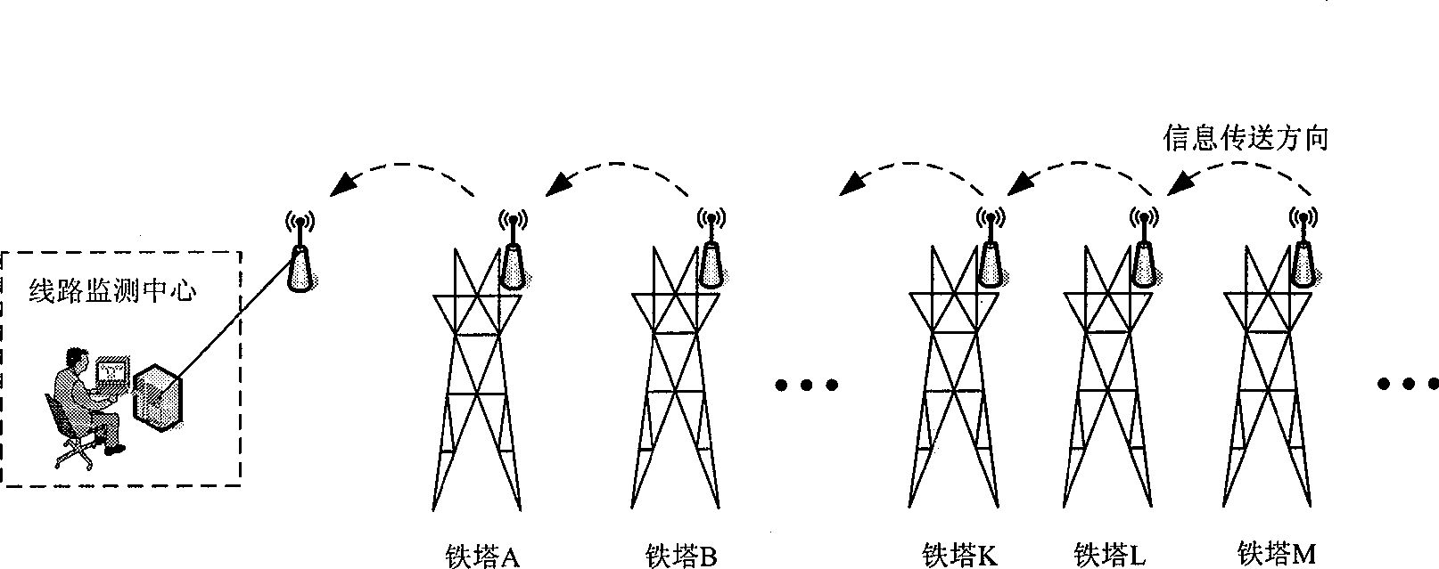
[0029] The purpose of the present invention is to overcome the defects of difficult implementation, functional limitations, inconvenient deployment, small bandwidth, high operating cost, low reliability, and inconvenient management and maintenance in the prior art, thereby providing a high-voltage transmission line monitoring based on wireless communication and optical communication method, which combines wireless Ad Hoc network technology and optical fiber communication technology, and can transmit the information monitored by thousands of sensors installed on iron towers at all levels back to the central station, so as to realize the monitoring of the entire high-voltage transmission line. real-time monitoring

Method used


Image

  • High voltage electricity transmission line monitoring method based on wireless communication and optical communication
  • High voltage electricity transmission line monitoring method based on wireless communication and optical communication
  • High voltage electricity transmission line monitoring method based on wireless communication and optical communication

Examples


Embodiment Construction

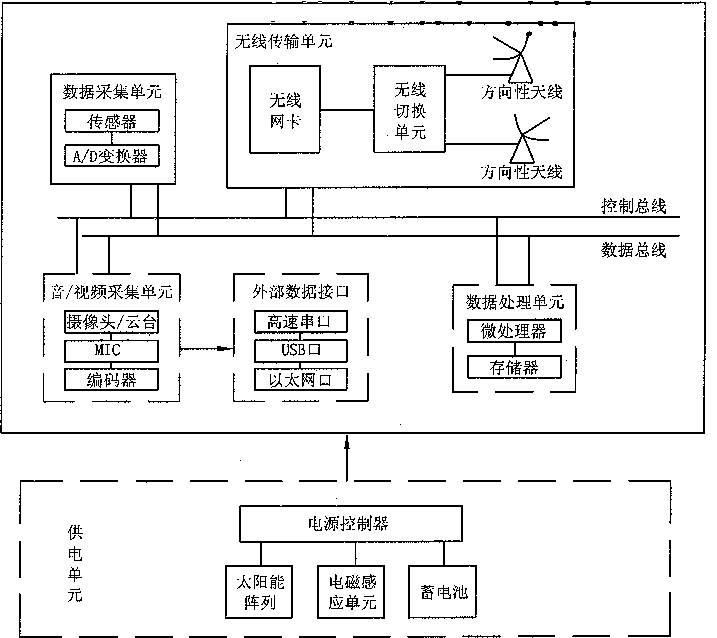
[0055] The invention installs special sensors and wireless communication equipment on the top of the iron tower of the transmission line. The wireless communication equipment on the towers at all levels, that is, the wireless monitoring nodes, form a wireless Ad Hoc network with self-organization and self-adaptation capabilities. Using the multi-hop transmission capability of the Ad Hoc network, the wireless nodes on the towers at all levels in a certain area can relay the monitoring information and transmit it to the optical communication nodes set up on the specific tower, that is, the convergence point tower. These optical communication nodes are connected to each other through the power special optical cables on the high-voltage transmission line, such as two optical fibers in OPGW or ADSS, to form an optical network with self-organizing characteristics similar to the Ad Hoc network. Each optical communication node also uses Data communication is carried out in a multi-hop mod...


PUM


Abstract

The invention relates to a high-tension transmission line monitoring method on the basis of wireless communication and photo-communication for overcoming the faults of limited functions, small band width, high running cost and low reliability in the prior art. The method comprises the following steps: 1. setting wireless monitoring nodes on the transmission line towers; selecting a particular tower along the line at an interval of 20-30 kilometers as a convergent point tower and simultaneously installing wireless monitoring nodes and photo-communication nodes on the convergent point tower and transforming plants on the two ends of the line; 2. the wireless monitoring nodes acquiring monitoring data, the wireless monitoring nodes of the towers in the area where the convergent point tower locates transmit the monitoring data to the photo-communication nodes on the convergent point tower by using a multi-hop forwarding method, each photo-communication node transmits the monitoring data to a monitoring center by using a multi-hop forwarding method. According to the invention, information monitored by thousands of sensors installed on towers of each level can be transmitted back to a junction centre for realizing the real-time monitoring of the whole high-tension transmission line.

Description

Technical field [0001] The invention relates to a method for monitoring a high-voltage power transmission line, in particular to a method for monitoring a high-voltage power transmission line based on wireless communication and optical communication. Background technique [0002] The electric power industry is an important basic industry and public utility related to the national economy and people's livelihood. The safe, stable and adequate supply of electric power is an important guarantee for the comprehensive, coordinated and sustainable development of the national economy. [0003] Transmission lines, especially high-voltage overhead transmission lines, are the lifeblood of the power system. The quality of their management not only directly affects the safe and stable operation of the power grid, but also affects the quality of power transmission. Therefore, strengthen the operation and management of transmission lines Vital. Under current technical conditions, line inspecti...

Claims


Application Information

Patent Timeline
Patent Type & Authority Applications(China)
IPC IPC(8): H04L12/28H04W84/18H02J13/00
CPCY02E60/723Y04S10/16Y02E60/00
Inventor 王炫张文柱刘扬周慧丛琳
Owner NORTHWEST CHINA GRID
Learn More