Method for controlling an electrically driven compressor

a compressor and electrical technology, applied in the direction of electric control, combustion engines, machines/engines, etc., can solve the problems of preventing the occurrence of “turbo lag” and ensuring the exhaust mass flow

Inactive Publication Date: 2005-08-02
VITESCO TECH GERMANY GMBH
View PDF6 Cites 19 Cited by
  • Summary
  • Abstract
  • Description
  • Claims
  • Application Information

AI Technical Summary

Benefits of technology

[0008]In a preferred embodiment of the invention, charge pressure control is provided which, in the case in which the electrically driven compressor is connected, activates the turbine with maximum power and controls the charge pressure using the electrical compressor power. This charge pressure control ensures that the electrically driven compressor is connected with minimum power in its connected state. At the same time the occurrence of “turbo lag” is prevented.

Problems solved by technology

A disadvantage of an exhaust gas turbocharger lies in the fact that a certain of exhaust mass flow is necessary to produce the required turbine power.
A further disadvantage of the turbocharger lies in the fact that mechanism first has to be accelerated before the required operating point is reached.
These disadvantages of the exhaust gas turbocharger lead to what is known as the “turbo lag”, which manifests itself as a delay in the case of positive jumps in load.

Method used


Image

  • Method for controlling an electrically driven compressor
  • Method for controlling an electrically driven compressor
  • Method for controlling an electrically driven compressor

Examples


Embodiment Construction

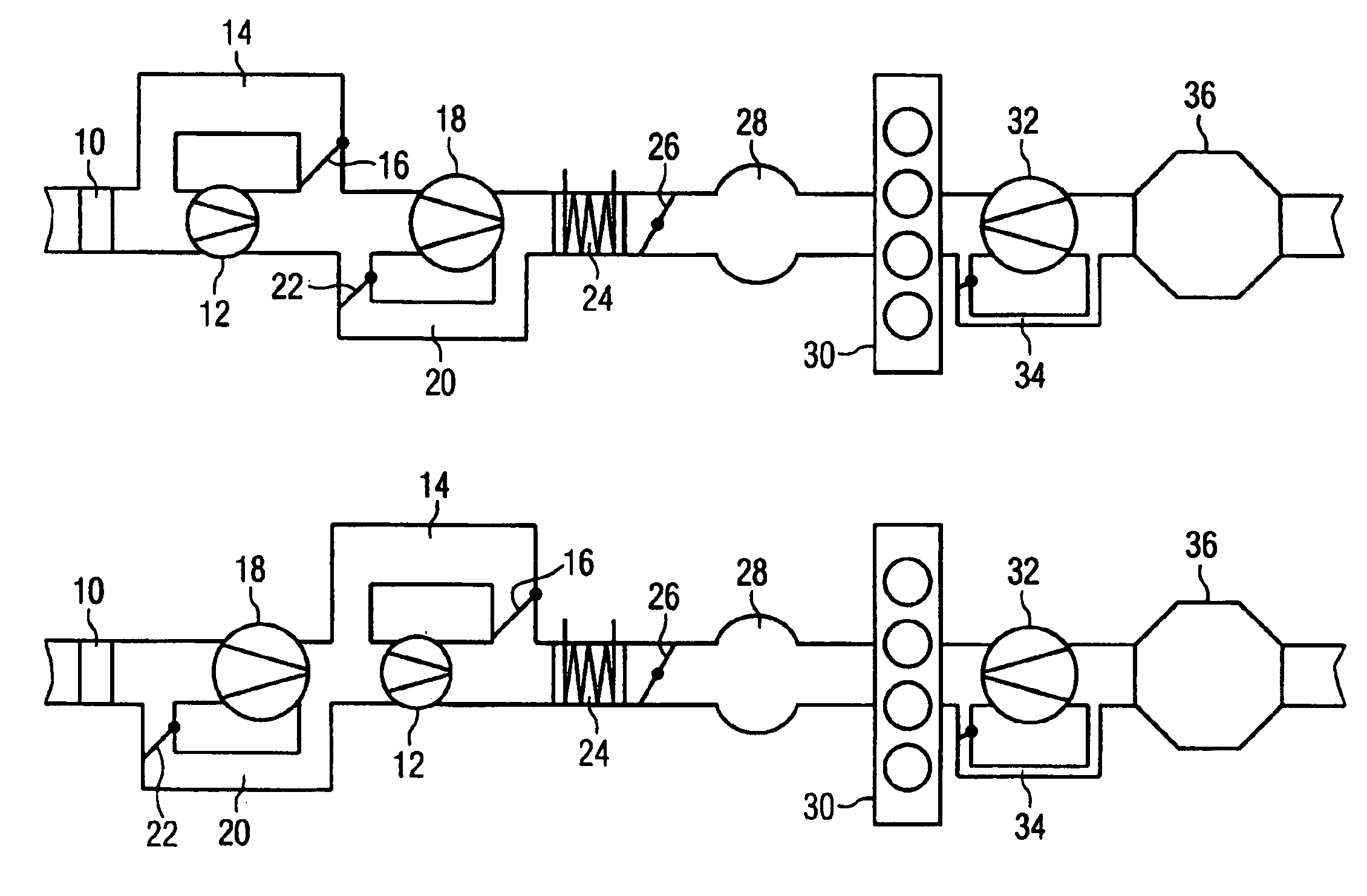
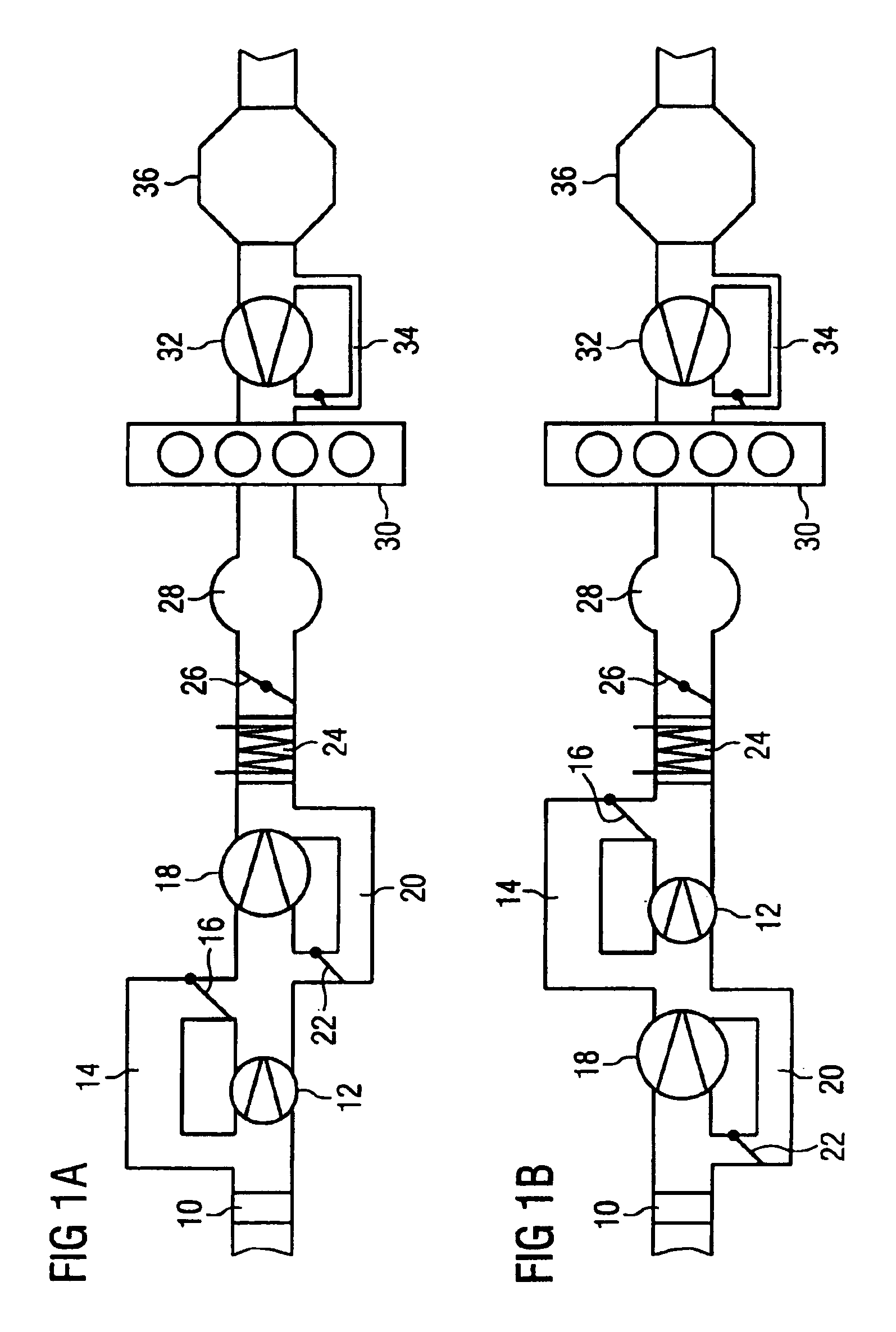
[0023]FIG. 1A shows a schematic overview diagram of register charging with an e-booster as an electrically driven compressor. The flow path depicted starts with an air filter 10. Downstream of the air filter 10 an e-booster 12 is provided. Parallel to the e-booster 12 there is a bypass channel 14, in which a controllable butterfly valve 16 is arranged. So that the electrically driven compressor 12 responds rapidly and provides the required pressure without any lag, this is a small design. To obtain a sufficient air mass flow with a small compressor the bypass channel 14 is provided.

[0024]Downstream from the e-booster 12 a compressor 18 of an exhaust gas turbocharger is provided. A bypass channel 20 with a controllable butterfly valve 22 is arranged in parallel to the compressor 18. The bypass channel 20 is opened at times to protect the exhaust gas turbocharger in order to pump air into the circuit at a corresponding pressure quotient via the compressor 18 of the exhaust gas turboch...


PUM


Abstract

An electrical booster in an internal combustion engine with an exhaust gas turbocharger is activated so that the electrical booster is connected with the minimum possible power consumption. The connection of the electric booster depends on the power balance, the electric booster being activated when the instantaneously available compressor power of the exhaust gas turbocharger is insufficient to provide the necessary power.

Description

CLAIM FOR PRIORITY[0001]This application is a continuation of International Application No. PCT / DE03 / 00018 which was filed on Jan. 7, 2003 and published on Jul. 24, 2003 and which claims the benefit of priority to German Application No. 102 02 146.5 filed Jan. 21, 2002.TECHNICAL FIELD OF THE INVENTION[0002]The invention relates to a method for controlling an electrically driven compressor in a internal combustion engine with an exhaust gas turbocharger.BACKGROUND OF THE INVENTION[0003]To increase the power of internal combustion engines exhaust gas turbochargers are used which compress the inlet air in order to increase the air throughput of the engine.[0004]A disadvantage of an exhaust gas turbocharger lies in the fact that a certain of exhaust mass flow is necessary to produce the required turbine power. A further disadvantage of the turbocharger lies in the fact that mechanism first has to be accelerated before the required operating point is reached. These disadvantages of the e...

Claims


Application Information

Patent Timeline
Patent Type & Authority Patents(United States)
IPC IPC(8): F02D41/00F02B37/18F02B39/02F02B37/04F02B39/10F02B37/12
CPCF02B37/04F02B37/12F02B37/18F02B39/10F02D41/0007F02D2041/1433F02D2041/1434Y02T10/144Y02T10/12
Inventor ELLMER, DIETMARSTURTZ, MICHAELTEINER, MARKUS
Owner VITESCO TECH GERMANY GMBH
Why Eureka
Try Eureka