Obstacle recognition system and obstacle recognition method

a recognition system and obstacle technology, applied in the direction of reradiation, pedestrian/occupant safety arrangement, instruments, etc., can solve the problems of difficult to recognize obstacles, inaccurate recognition of objects by millimeter wave radar, and inability to perform appropriate obstacle recognition

Active Publication Date: 2009-08-04
TOYOTA JIDOSHA KK
View PDF19 Cites 200 Cited by
  • Summary
  • Abstract
  • Description
  • Claims
  • Application Information

AI Technical Summary

Benefits of technology

[0027]The present invention involves the execution of the obstacle detection with the radar on the basis of the image information, and thus implements appropriate recognition of the obstacle.

Problems solved by technology

However, this system has a problem that appropriate obstacle recognition is not performed.
For example, where there exists an object with low reflection of waves, the millimeter wave radar fails to perform accurate recognition of the object.
In a reverse case where there exists an object with large reflection of waves, the object, such as a metal bump on a road, poses no serious impediment to vehicle travel in some situations, and it makes appropriate recognition of an obstacle difficult.

Method used


Image

  • Obstacle recognition system and obstacle recognition method
  • Obstacle recognition system and obstacle recognition method
  • Obstacle recognition system and obstacle recognition method

Examples


Embodiment Construction

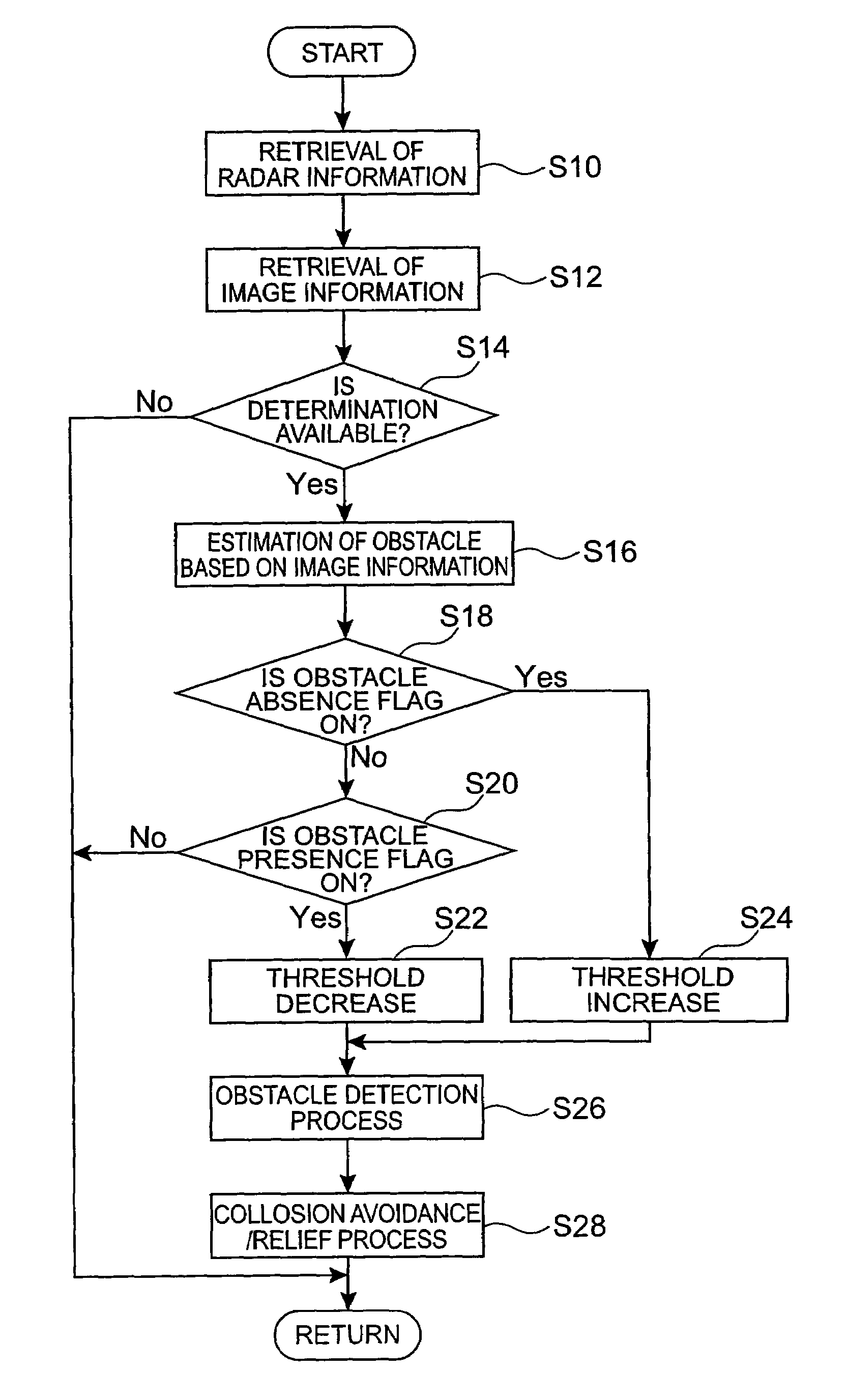
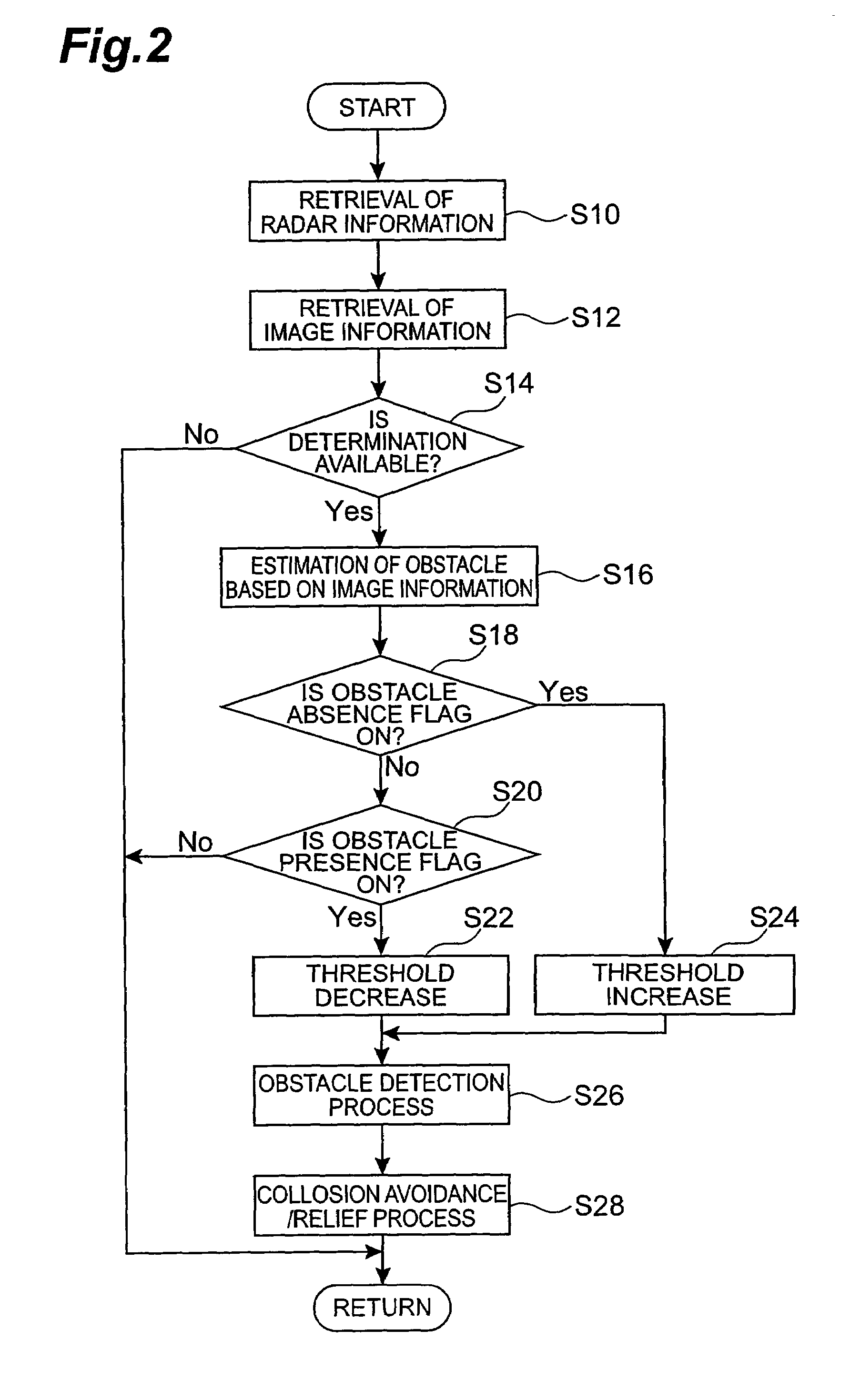
[0035]An embodiment of the present invention will be described below in detail with reference to the accompanying drawings. The same elements will be denoted by the same reference symbols in the description of the drawings, without redundant description.

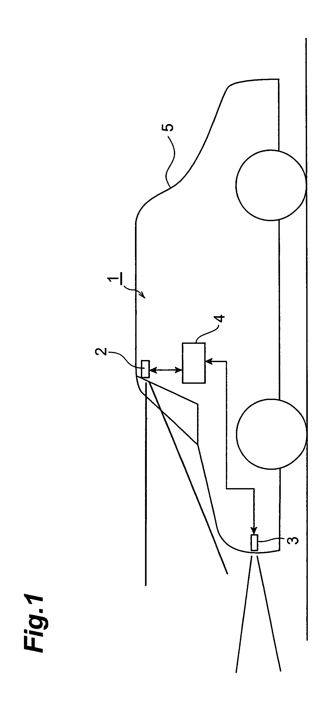
[0036]FIG. 1 is a schematic view of a configuration of an obstacle recognition system according to an embodiment of the present invention.

[0037]As shown in FIG. 1, the obstacle recognition system 1 of the present embodiment is a device mounted on a vehicle 5, and device for detecting an obstacle in front of the vehicle 5. This obstacle recognition system 1 is provided with an image taking part 2. The image taking part 2 functions as an image taking means for taking an image of an object around the vehicle, and is installed, for example, so as to take a forward image ahead the vehicle 5. This image taking part 2 is, for example, a CCD camera or a C-MOS camera.

[0038]The obstacle recognition system 1 has a radar 3. The radar 3 is a devi...


PUM


Abstract

The present invention relates to an obstacle recognition system and an obstacle recognition method. A radar detects existence of an object around a vehicle, an image taking part such as a camera takes an image of the object around the vehicle, a determination threshold is set at a low value when it is determined based on image information of the photographic image that a possibility of presence of an obstacle is high, the determination threshold is set at a high value when it is determined that the possibility of the presence of the obstacle is low, and these determination threshold values are used to detect the obstacle to travel of the vehicle on the basis of the output from the radar.

Description

BACKGROUND OF THE INVENTION[0001]1. Field of the Invention[0002]The present invention relates to an obstacle recognition system and an obstacle recognition method for effecting recognition of an obstacle to vehicle travel.[0003]2. Related Background of the Invention[0004]An example of the conventionally known obstacle recognition systems is one having a millimeter wave radar and an image acquiring means, as described in Japanese Patent Application Laid-Open No. 2001-296357. This system is configured to specify an image recognition area on the basis of the power from the millimeter wave radar, to execute image processing for detection of an object within the limited image recognition area thus specified, and thereby to reduce the time of the image processing.SUMMARY OF THE INVENTION[0005]However, this system has a problem that appropriate obstacle recognition is not performed. For example, where there exists an object with low reflection of waves, the millimeter wave radar fails to p...

Claims


Application Information

Patent Timeline
Patent Type & Authority Patents(United States)
IPC IPC(8): G01S13/00G06K9/00B60R21/00B60R21/01B60R21/02B60R21/055B60R22/46B62D6/00G01S7/40G01S7/497G01S13/86G01S13/931G01S17/87G01S17/931G05D1/02G08G1/16
CPCG01S7/4004G01S13/931G01S13/867G01S7/497G01S17/87G01S2013/9375G01S2013/9342G01S2013/9346G01S17/936G01S2013/93185G01S2013/93271G01S2013/9318G01S17/931
Inventor TOKORO, SETSUO
Owner TOYOTA JIDOSHA KK
Why Eureka
Try Eureka