Dielectric waveguide device, phase shifter, high frequency switch, and attenuator provided with dielectric waveguide device, high frequency transmitter, high frequency receiver, high frequency transceiver, radar device, array antenna, and method of manufacturing dielectric waveguide device

a dielectric waveguide and phase shifter technology, applied in waveguides, waveguides, array antennas, etc., can solve the problems of difficult to achieve a small and low-voltage operable dielectric waveguide device, high voltage of 4000 v, and high voltage, so as to reduce the wavelength of propagating electromagnetic waves and reduce the size. , the effect of small siz

Inactive Publication Date: 2011-09-06
KYOCERA CORP
View PDF20 Cites 239 Cited by
  • Summary
  • Abstract
  • Description
  • Claims
  • Application Information

AI Technical Summary

Benefits of technology

[0017]The respective second dielectric parts function as a support member for supporting the plate conductor parts. Therefore, the plate conductor parts can be manufactured by using a thin film forming technology, a thick film printing technology, or a sheet-like ceramic technology, and thus in manufacturing, a dielectric waveguide device suitable for reduction in size can be achieved.
[0156]According to the invention, it is possible to achieve the phase shifter in which even-numbered electrode films and odd-numbered electrode films in the lamination direction from among the electrode films are connected to different plate conductor parts. In addition, the laminated electrode films can be accurately and reliably led to the first end face and the second end face. Therefore, a manufacturing method suitable for a known semiconductor process is provided, and thus a small, accurate, and stable dielectric waveguide device can be manufacturing with good mass productivity. The dielectric waveguide device is a phase shifter, a high frequency switch, an attenuator or the like.

Problems solved by technology

For this reason, there is a problem in that a high voltage of 4000 V should be applied.
As such, in the related art, it is difficult to achieve a small and low-voltage operable dielectric waveguide device with a dielectric body which varies in dielectric constant depending on the magnitude of an applied electric field.

Method used


Image

  • Dielectric waveguide device, phase shifter, high frequency switch, and attenuator provided with dielectric waveguide device, high frequency transmitter, high frequency receiver, high frequency transceiver, radar device, array antenna, and method of manufacturing dielectric waveguide device
  • Dielectric waveguide device, phase shifter, high frequency switch, and attenuator provided with dielectric waveguide device, high frequency transmitter, high frequency receiver, high frequency transceiver, radar device, array antenna, and method of manufacturing dielectric waveguide device
  • Dielectric waveguide device, phase shifter, high frequency switch, and attenuator provided with dielectric waveguide device, high frequency transmitter, high frequency receiver, high frequency transceiver, radar device, array antenna, and method of manufacturing dielectric waveguide device

Examples


Embodiment Construction

[0201]Now referring to the drawings, preferred embodiments of the invention are described below.

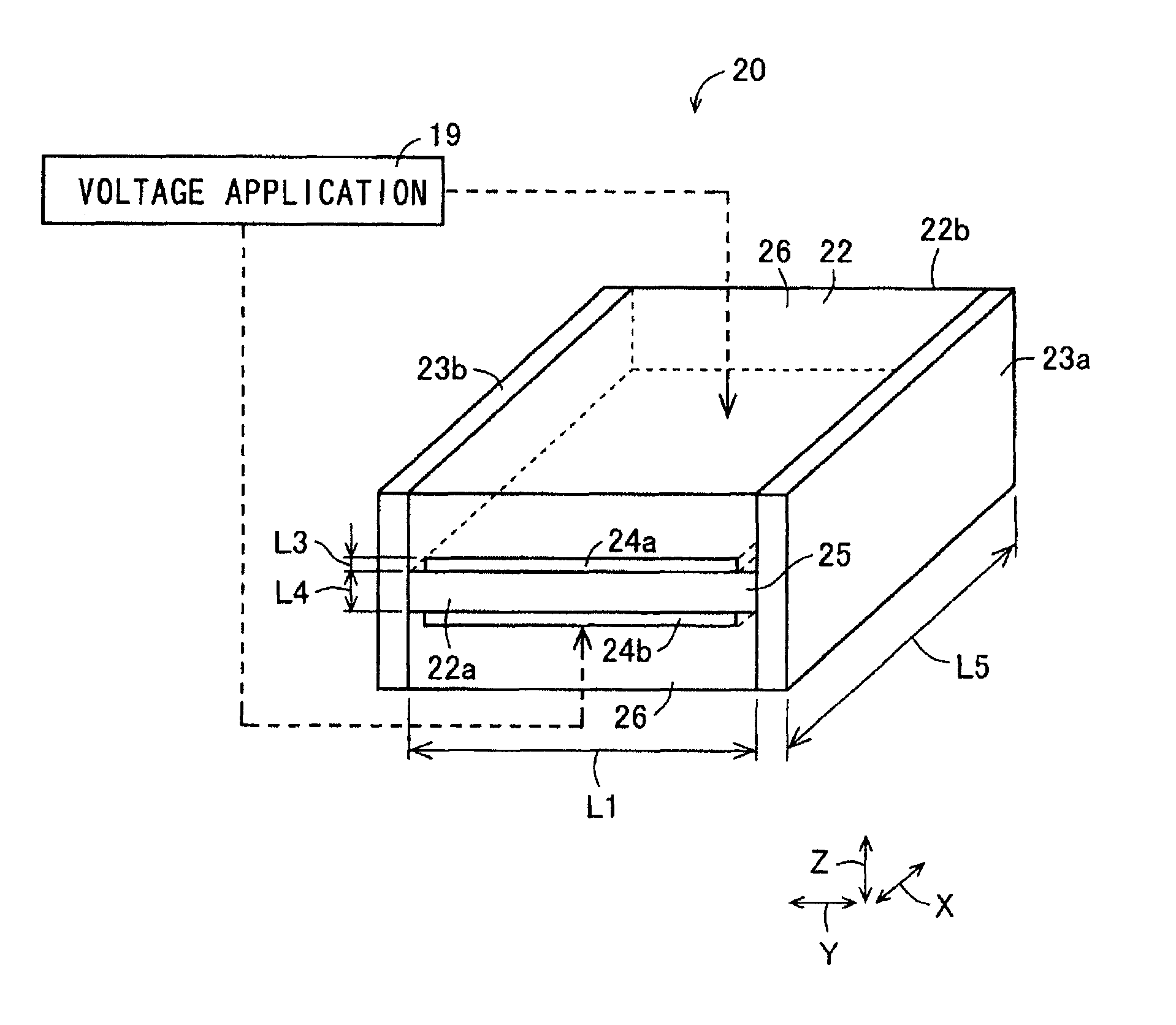
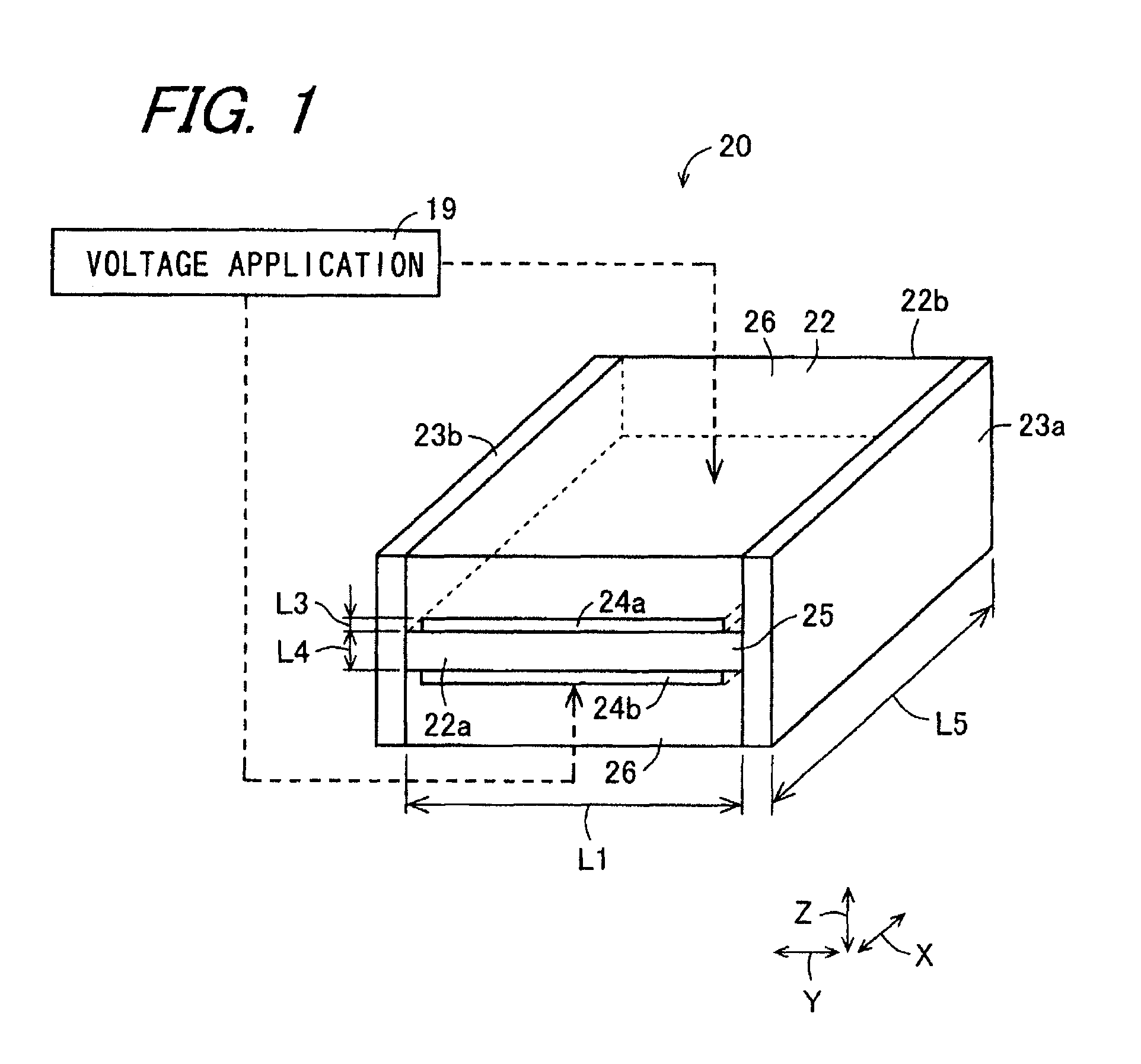
[0202]FIG. 1 is a perspective view schematically showing a phase shifter 20 according to an embodiment of the invention. The phase shifter 20 includes a dielectric part 22, a pair of first and second plate conductor parts 23a and 23b, a pair of first and second electrodes 24a and 24b, and a voltage application unit 19. The phase shifter 20 according to the embodiment of the invention substantially has a rectangular parallelepiped shape. A section of the phase shifter 20 perpendicular to a propagation direction X of electromagnetic wave has the same shape as an end face of the phase shifter 20 in the propagation direction X.

[0203]The dielectric part 22 is made of a dielectric, and includes a first dielectric part 25 having a variable part which varies in dielectric constant depending on an applied electric field and second dielectric parts 26. The dielectric part 22 has a first input / outpu...


PUM

PropertyMeasurementUnit
voltageaaaaaaaaaa
dielectric constantaaaaaaaaaa
volume resistivityaaaaaaaaaa

Abstract

The invention relates to a small and low-voltage operable dielectric waveguide device. First and second electrode are embedded in a dielectric part and are formed to be thinner than a skin depth for a frequency of electromagnetic wave propagating along a first dielectric part included in the dielectric part. Thereby, even if the first and second electrodes are arranged to be in contact with the first dielectric part, the propagating electromagnetic wave can transmit the first and second electrodes, and therefore the electromagnetic wave can propagate without being cut off and there is no influence on waveguide modes of the electromagnetic wave. Further, in a state where a transmission loss due to the embedded of the electrode is suppressed, an electric field with large electric field strength can be applied to the first dielectric part by the first and second electrodes, and a small and low-voltage operable dielectric waveguide device can be achieved.

Description

TECHNICAL FIELD[0001]The present invention relates to a dielectric waveguide device for use at high frequency band, such as a microwave band, a submillimeter wave band, or a millimeter wave band, a phase shifter, a high frequency switch and an attenuator, which control the phase of electromagnetic wave at the high frequency band, a high frequency transmitter, a high frequency receiver, a high frequency transceiver, a radar device, an array antenna, and a method of manufacturing a dielectric waveguide device.BACKGROUND ART[0002]A first example of related art is a phase shifter serving as a dielectric waveguide device that has a coplanar waveguide formed on a ferroelectric thin film and changes the phase of electromagnetic wave by applying a voltage to the ferroelectric thin film (for example, see Japanese Patent Application National Publication JP-A 2003-508942).[0003]A second example of related art is a phase shifter serving as a dielectric waveguide device that has a parallel and f...

Claims


Application Information

Patent Timeline
Patent Type & Authority Patents(United States)
IPC IPC(8): H01P3/00
CPCG01S7/03H01P3/165H01P1/18Y10T29/49155G01S7/02H01P3/16
Inventor HIRAMATSU, NOBUKISAGALA, DJUNIADI A.KISHINO, TETSUYA
Owner KYOCERA CORP
Why Eureka
Try Eureka