Antenna for a level meter employing the radar principle

a level meter and antenna technology, applied in the direction of antennas, antenna supports/mountings, liquid/fluent solid measurement, etc., can solve the problem of negative effect of dielectric properties

Inactive Publication Date: 2010-03-23
KROHNE MESSTECHNICK GMBH & CO KG
View PDF12 Cites 235 Cited by
  • Summary
  • Abstract
  • Description
  • Claims
  • Application Information

AI Technical Summary

Problems solved by technology

In practical use, however, it has been found that any such bonding is fraught with problems in that it either has a negative effect on the dielectric properties, and thus for instance on the beam characteristics of the antenna, or, depending on the type of bonding, only certain dielectric materials can be used.

Method used


Image

  • Antenna for a level meter employing the radar principle
  • Antenna for a level meter employing the radar principle
  • Antenna for a level meter employing the radar principle

Examples


Embodiment Construction

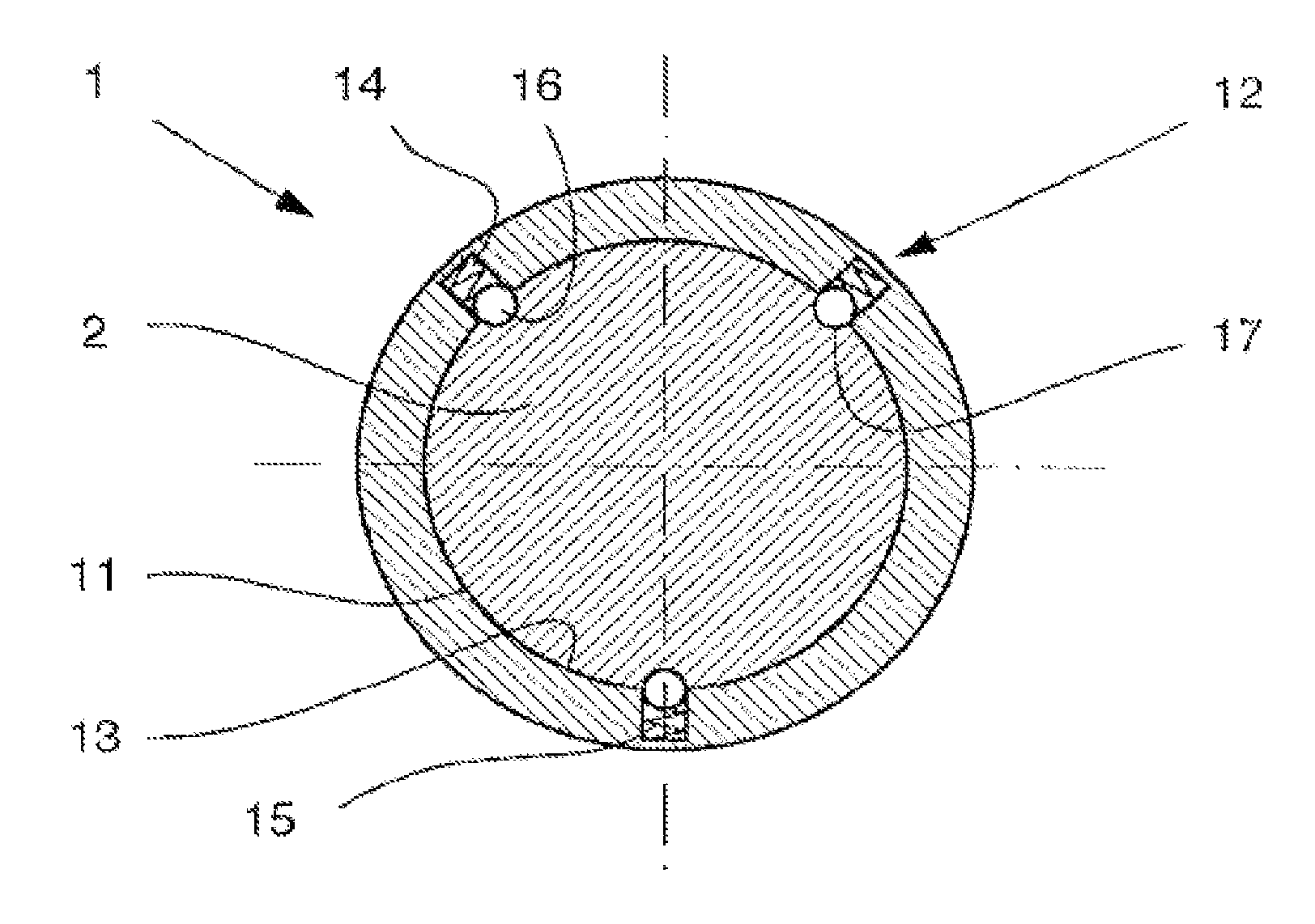
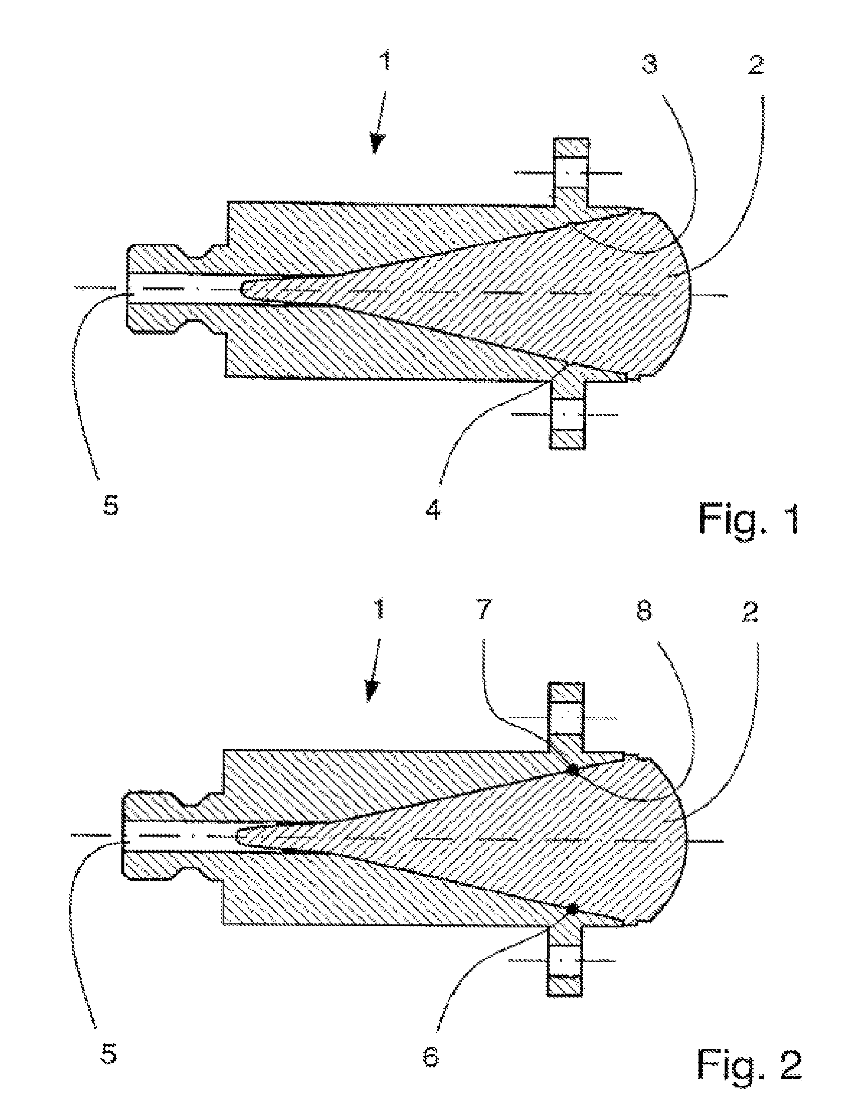
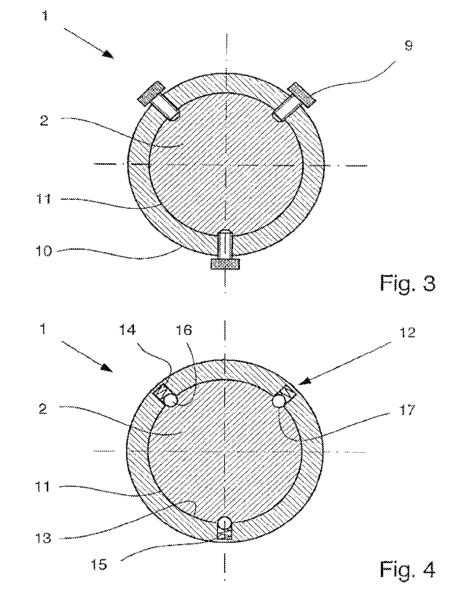
[0022]FIG. 1 is a longitudinal section view of an antenna for a radar-type level meter. The antenna is a horn antenna 1 in which a dielectric PTFE insert 2 is installed. The dielectric insert 2 is mounted in the horn antenna 1 in removable fashion, the fastening device in this case being a continuous clamping collar 3. This clamping collar 3 is integrally molded onto the outer wall of the dielectric insert 2 and consists of the same PTFE material. The inner wall of the horn antenna 1 is provided with a clamping recess 4 matching and accepting the clamping collar 3.

[0023]When the horn antenna 1 is made of a metal such as stainless steel and the dielectric PTFE insert 2 is shaped as described above, a certain degree of elasticity and compressibility of the PTFE material allows the dielectric insert 2 to be snapped into the inside of the horn antenna 1 when a light axial pressure is applied.

[0024]To loosen the dielectric insert 2 so that it can be removed from the horn antenna 1, for i...


PUM


Abstract

In an antenna for a level meter employing the radar principle, a fastening device is provided for detachably mounting a dielectric insert in the antenna. The fastening device may be a continuous clamping collar that clamps the dielectric insert in place in the antenna. This offers a simple, universally employable possibility for fastening a dielectric insert in the antenna.

Description

BACKGROUND OF THE INVENTION[0001]This invention relates to an antenna, equipped with a dielectric insert, for use with a level meter that operates employing the radar principle.[0002]A horn antenna for radar systems, its antenna cavity filled at least partly by a dielectric insert, has been described earlier, for instance, in DE 100 57 441 A1. Radar-type level meters utilizing that principle are used for measuring the level of liquids and granular materials. A microwave beam is transmitted via an antenna and is recaptured upon reflection off the surface of the medium being measured. The level of the medium can be calculated, for instance, by means of a runtime measurement.[0003]As described in DE 100 57 441 A1, there are various applications for which the antenna of a radar-based level meter needs to be equipped with a dielectric insert. According to the description in that publication, the dielectric material is applied, for example, by being molded into the antenna interior. That ...

Claims


Application Information

Patent Timeline
Patent Type & Authority Patents(United States)
IPC IPC(8): H01Q13/00
CPCG01F23/284H01Q19/08H01Q1/225
Inventor GERDING, MICHAELMATT, ACHIMMUSCH, THOMAS
Owner KROHNE MESSTECHNICK GMBH & CO KG
Why Eureka
Try Eureka