Waveguided laser channels for a gas laser

Active Publication Date: 2009-08-04
EPILOG CORP
View PDF37 Cites 23 Cited by
  • Summary
  • Abstract
  • Description
  • Claims
  • Application Information

AI Technical Summary

Benefits of technology

[0011]The RF-excited waveguide gas laser module in accordance with the present invention has a waveguide channel which maximizes higher order mode suppression and maximizes uniform discharge formation. The waveguide channel in accordance with the present invention further provides excellent gas venting to eliminate acoustical distortion. The elongate gaps incorporated into the waveguide channel provide a particle exit out of the waveguide channel to minimize the likelihood of damage to the laser optics in the event a particle

Problems solved by technology

One problem with a waveguide laser assembly as taught in Hart is the springs 26 as well as the sandwich assembly are slid into a housing interior and the lateral movement between the spring, the sandwiched assembly and the housing interior can generate particles which later can damage the optics in the manner described above.
Yet another problem with existing RF-excited waveguide gas lasers is that harmonic acoustic resonance during pulsed operation within the waveguide laser channels can adversely affect laser performance.
While such openings may be so

Method used


Image

  • Waveguided laser channels for a gas laser
  • Waveguided laser channels for a gas laser
  • Waveguided laser channels for a gas laser

Examples


Example

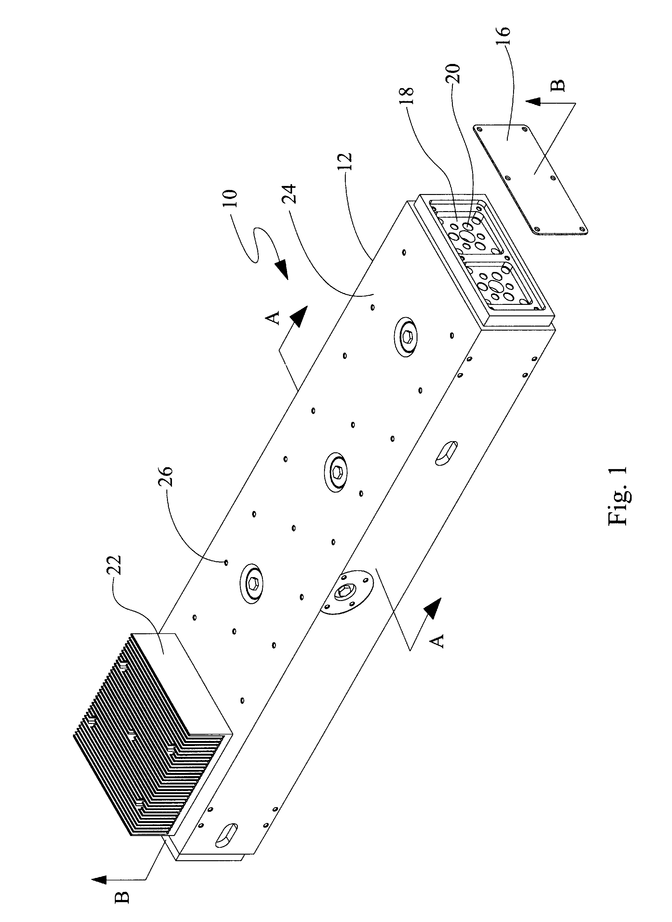
[0020]A partially assembled RF-excited waveguide gas laser module 10 is illustrated in FIG. 1. The module 10 comprises a housing 12 containing a waveguide laser assembly 14 shown exploded in FIG. 2. An end panel 16 is shown removed from the housing to reveal optic adjustment plates 18 having holes 20 for accessing optics adjustment screws as known in the art. A heat sink 22 is shown attached in abutment to a top surface 24 of the housing 12. Screw holes 26 are also provided in the top surface 24 of the housing 12 for attaching other heat sinks, which are not shown for the sake of clarity.

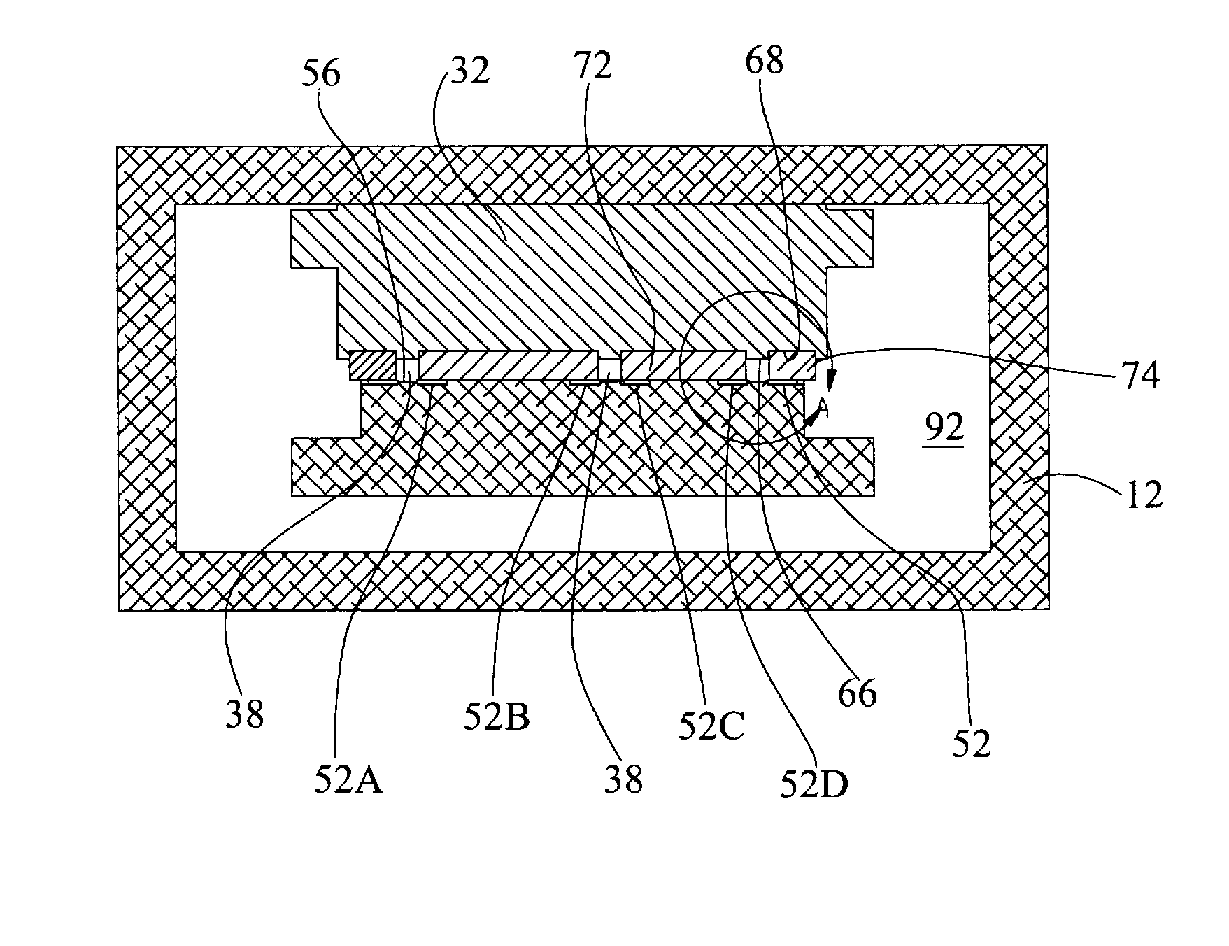
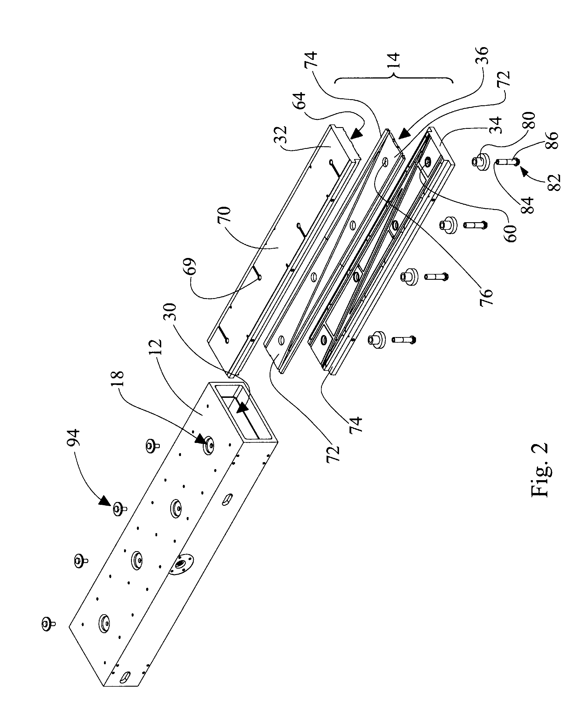
[0021]Referring to FIG. 2, the waveguide laser assembly 14 is shown exploded and removed from a cavity 30 of the housing 12. The waveguide laser assembly 14 comprises a first electrode 32, a second electrode 34 and a dielectric insert assembly 36. Either or both electrodes could be active or “hot”. However, in the embodiment discussed herein the second electrode is the active electrode and the first...


PUM


Abstract

An RF-excited waveguide laser module comprises a first electrode having a first elongate surface defining in part a waveguide laser channel extending along an optical axis, the first elongate surface having a substantially linear cross-section normal to the optical axis. A second electrode has a second elongate surface defining in part the waveguide laser channel extending along the optical axis. The second elongate surface has a non-linear cross-section normal to the optical axis. A dielectric insert may be provided between the electrodes defining in part the waveguide laser channel. A lengthwise gap may extend essentially an entire length of the waveguide laser channel between one of the first and second electrodes and the dielectric insert. The gap provides fluid communication between the waveguide laser channel and a volume outside the waveguide laser channel.

Description

RELATED APPLICATIONS[0001]This application claims priority from U.S. Provisional Patent Application Ser. No. 60 / 778,513, filed Mar. 1, 2006, entitled “Improved Method of Assembling RF-Excited Waveguide Gas Lasers and Improved Wave Guiding Laser Channels,” which is hereby incorporated by reference.TECHNICAL FIELD[0002]The present invention is directed to RF-excited waveguide gas lasers and more particularly, to improved waveguide laser channels.BACKGROUND OF THE INVENTION[0003]RF-excited waveguide gas lasers are finding more applications as their reliability improves and their costs decrease. One of the keys to improving reliability is eliminating the presence of any particles which may intrude in the waveguide laser channels and smash into and damage the laser optics. One typical RF-excited waveguide laser assembly is described in Hart, U.S. Pat. No. 6,192,061. The RF-excited waveguide laser assembly of Hart consists of a pair of electrodes with dielectric waveguide insert sandwiche...

Claims


Application Information

Patent Timeline
IPC IPC(8): H01S3/22
CPCH01S3/03H01S3/0315H01S3/0385H01S3/076H01S3/0388
Inventor BRODERICK, JEFFERY ADORAN, JOHN HGARNIER, STEVEN FMITCHINER, CHAD A
Owner EPILOG CORP
Why Eureka
Try Eureka