Device for demarcating an area

a technology for demarcating devices and areas, applied in automatic actuation, applications, instruments, etc., can solve the problems of large force exerted on the structure of tracking arms, wire fencing breaking, lateral biasing forces acting on guide wires, etc., and achieve accurate drive and control

Inactive Publication Date: 2009-08-11
LELY ENTERPRISES
View PDF9 Cites 5 Cited by
  • Summary
  • Abstract
  • Description
  • Claims
  • Application Information

AI Technical Summary

Benefits of technology

[0008]According to a further inventive feature, the vehicle has a length in the direction of the guide wire and the tension force is exerted at an equilibrium position along the length of the vehicle. For a wheeled vehicle having front and rear wheels, the tension force, seen in plan view, is exerted in the middle between the wheels. This results in that each wheel experiences an almost equal moment that is exerted on the vehicle by the tension force, which has the advantage that the vehicle is better controllable during driving. In order to provide the wheels of the vehicle with sufficient grip on the ground, according to the invention, the wheels are designed as cage wheels, the running surface of the cage wheels being constituted by spaced apart, circularly curved strips. The circularly curved strips further have the advantage that the running surface of the wheels is approximately equal to the running surface of a normal pneumatic tyre, which is advantageous to the maneuverability of the vehicle.
[0009]According to again another inventive feature, the vehicle comprises two pairs of cage wheels that are drivable independently of each other, each pair of cage wheels comprising a drive chain. Owing to the fact that the wheels can be driven in pairs, it is possible to control the vehicle with the aid of the separate drive of the wheel pairs. Furthermore, in relation to for example a drive belt, the drive chain has the advantage of demonstrating hardly any slip or no slip at all, which enables a very accurate drive and control.
[0010]According to again another aspect of the invention, at least the first vehicle is provided with stretching means, the stretching means comprising a reel or other appropriate rolling means drivable by an electric motor or the like for rolling and unrolling the demarcating element. The reel is preferably connected to the vehicle in a first suspension point by means of a load cell and in a second suspension point by means of a leaf spring. The advantage of using a leaf spring suspension is a very predictable load of an accurate power measurement in the load cell.
[0012]Although the invention may be performed with a single vehicle, e.g. operating along a circular path, according to again another inventive feature, a second or further vehicle may also be provided and the demarcating element may be tensioned between the vehicles. The second vehicle may also comprise a guiding piece that is rotatable about a vertical axis. In order to prevent the guide wire and / or parts of the vehicle from breaking down or becoming damaged by excess tension, according to an inventive feature, the guiding piece comprises a break-back device to which the demarcating element is attachable. In a preferred embodiment according to the invention, the break-back device is designed as a spring break-back device comprising preferably a screw-shaped bending spring with a circular section. In order to make it possible to measure the stretching force exerted by the demarcating element on a vehicle, according to an inventive feature, the guiding piece is provided with a load cell. In order to make it possible to measure the angular rotation of the demarcating element relative to the vehicles, according to an inventive feature, the guiding piece comprises an angle measuring instrument with the aid of which the angular rotation about the vertical axis can be determined.
[0013]According to again another aspect of the invention, the second vehicle is also provided with a tracking arm structure for making it possible to track a second guide wire disposed in the area.
[0014]According to a further inventive feature, the tracking arm structure used on either the tracking vehicle or the second vehicle or both, is provided with a tracking element for tracking the guide wire. According to a further inventive feature, the tracking element is designed in such a way that it engages the guide wire at least two spaced apart points of engagement. According to a further inventive feature, at said points of engagement, the tracking element is provided with bracket-shaped elements for enclosing the guide wire. According to a further inventive feature, each of the bracket-shaped elements is provided at its lower side with a closing element that can be opened against spring action. Said closing element makes it possible for the tracking arm structure to pass fastening elements of a guide wire disposed in the area.

Problems solved by technology

This known device has the disadvantage that the stretched wires between the two vehicles are directly connected with the tracking arm structures, which results in great forces being exerted on the tracking arm structures when relatively long wires are stretched between the vehicles.
Also the forces exerted by the tracking arm structures on the wire fencings by means of the hooks can lead to the wire fencing breaking in those cases where excess loads are exerted upon it.
As mentioned above, such lateral biasing forces acting on a guide wire have been found generally undesirable, requiring more substantial structures to support the guide wire.

Method used


Image

  • Device for demarcating an area
  • Device for demarcating an area
  • Device for demarcating an area

Examples


Embodiment Construction

[0024]The following is a description of an embodiment of the invention, given by way of example only and with reference to the drawings.

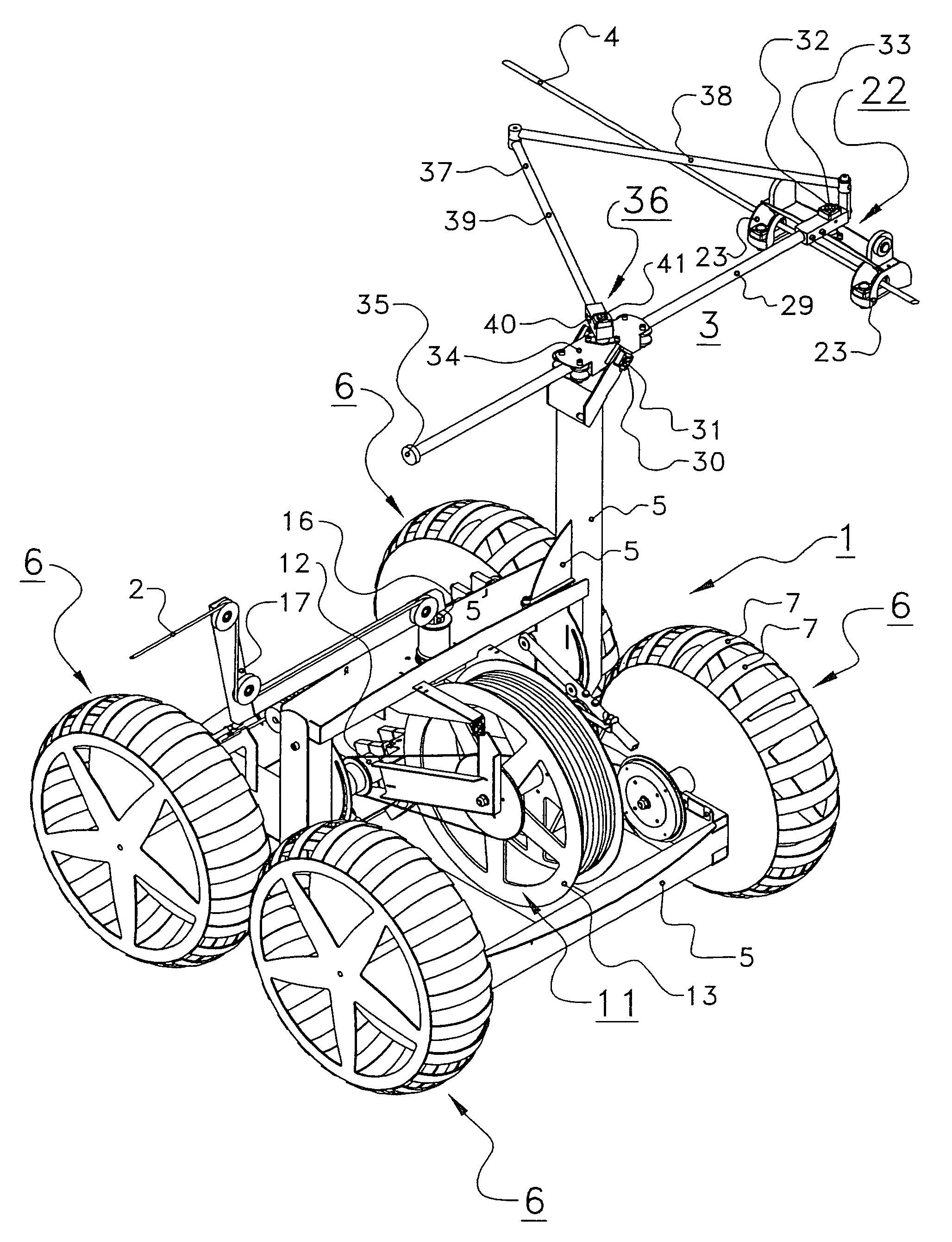
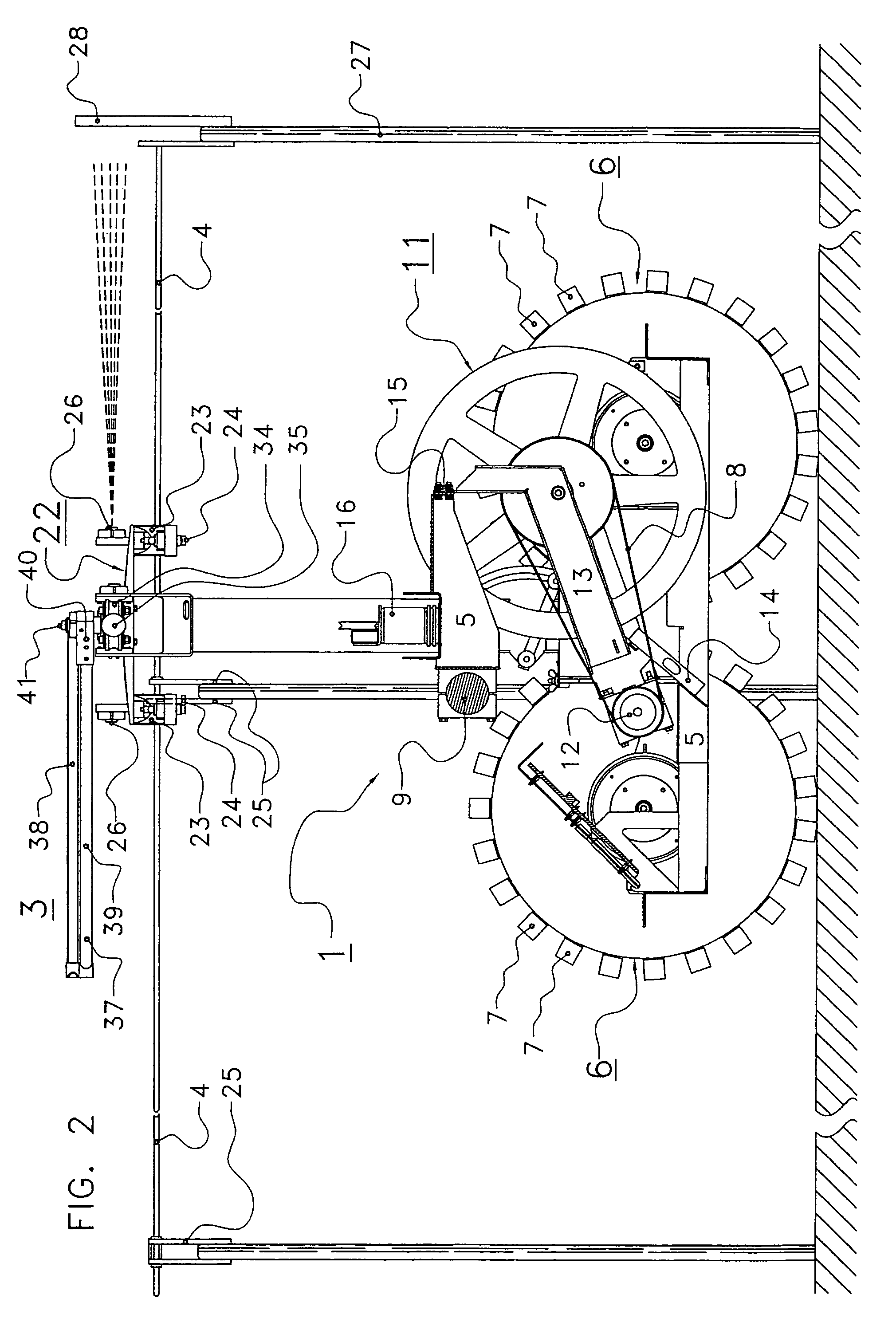
[0025]FIG. 1 shows a first unmanned vehicle 1 that is provided with a demarcating element 2 and a tracking arm structure 3 for making it possible to track a guide element 4 disposed in an area. In the present embodiment, both the demarcating element 2 and the guide element 4 are designed as wires that can be electrified. The first vehicle 1 comprises a frame structure 5 with four cage wheels 6. The cage wheels 6 have a running surface that is constituted by spaced apart, circularly curved strips 7. Both the left and the right pair of cage wheels 6 comprise a drive chain 8 that drives one pair of cage wheels 6 simultaneously by means of an electric step motor 9 that is disposed on the frame structure 5 for each pair of cage wheels 6 separately (see FIG. 3). By driving the electric step motors 9 simultaneously or independently of each other, the unman...


PUM


Abstract

A device for demarcating an area, in particular for limiting the freedom of movement of animals walking about freely, is provided with a demarcating element (2) that is connected with a first vehicle (1) and with at least a second vehicle (10). At least the first vehicle (1) is provided with a tracking arm structure (3) for making it possible to track a guide element (4) disposed in the area, such as for example a wire fencing. The demarcating element (2) is disposed in a stretched position between the two vehicles (1, 10) in such a way that the demarcating element (2) does not exert force on the tracking arm structure (3).

Description

CROSS REFERENCE TO RELATED APPLICATIONS[0001]This application claims priority from Dutch application number 1029600 filed on 25 Jul. 2005, the contents of which are hereby incorporated by reference in their entirety.BACKGROUND OF THE INVENTION[0002]1. Field of the Invention[0003]The invention relates generally to a device for demarcating an area, in particular for limiting the freedom of movement of animals walking about freely.[0004]2. Description of the Related Art[0005]Devices are known for demarcating areas, in which a demarcating element is connected between a first vehicle and at least a second vehicle. At least the first vehicle is provided with a tracking arm structure for making it possible to track a guide element disposed in the area, such as for example a wire fencing. A device of this type is known from German Offenlegungsschrift DE 42 15 714. The known device comprises two tracked vehicles that are each provided with a tracking arm structure between which two wires are...

Claims


Application Information

Patent Timeline
Patent Type & Authority Patents(United States)
IPC IPC(8): G05D1/00
CPCA01K3/005A01K3/00A01K1/105
Inventor VLAAR, IWAN YVESVAN DEN BERG, KARELVAN KUILENBURG, JAN MARTINUS
Owner LELY ENTERPRISES
Why Eureka
Try Eureka