Radio-frequency identification tag communication device

a radio frequency identification and communication device technology, applied in the direction of transmission monitoring, near-field systems using receivers, instruments, etc., can solve the problems of communication device having a risk of failure to communicate with the desired radio-frequency identification tag, limited maximum distance of communication with the tag according to the conventional array antenna technique, etc., to maximize the signal-to-noise ratio and maximize the density of transmission power

Inactive Publication Date: 2009-08-11
BROTHER KOGYO KK
View PDF14 Cites 14 Cited by
  • Summary
  • Abstract
  • Description
  • Claims
  • Application Information

AI Technical Summary

Benefits of technology

[0010]As described above, the radio-frequency identification tag communication device according to the present invention comprises the directivity control portion operable to control the directivity of the transmitter antenna, and the adaptive weight control portion operable to implement the adaptive control of the weight to be given to the received signal received by each of the plurality of antenna elements, on the basis of the reply signal transmitted from the radio-frequency identification tag. Accordingly, the directivity of the transmitter antenna is changed to a direction in which the radio-frequency identification tag in question is expected to exist, and the weight to be given to each received signal is subjected to the adaptive control, so that the sensitivity of communication of the communication device with the radio-frequency identification tag is improved. Namely, the present radio-frequency identification tag communication device has an increased maximum distance of communication with the radio-frequency identification tag.
[0018]In a further preferred form of the invention, the adaptive weight control portion is operable to implement the adaptive control of the weight to be given to each of the received signals received by the plurality of antenna elements, so as to maximize a signal-to-noise ratio (a ratio of a desired signal to an interference signal) of a composite signal which is synthesized by combining together the received signals to which the weight has been given. Accordingly, the weight to be given to each received signal can be controlled in a practically effective manner.

Problems solved by technology

However, the plurality of radio-frequency identification tags with which the radio-frequency identification tag communication device communicates are usually located at mutually distant positions, and reflected waves transmitted from those tags have extremely low intensities, so that the maximum distance of communication with the tags according to the conventional array antenna techniques is limited, and the communication device has a risk of failure of communication with the desired radio-frequency identification tags.

Method used


Image

  • Radio-frequency identification tag communication device
  • Radio-frequency identification tag communication device
  • Radio-frequency identification tag communication device

Examples


embodiment 1

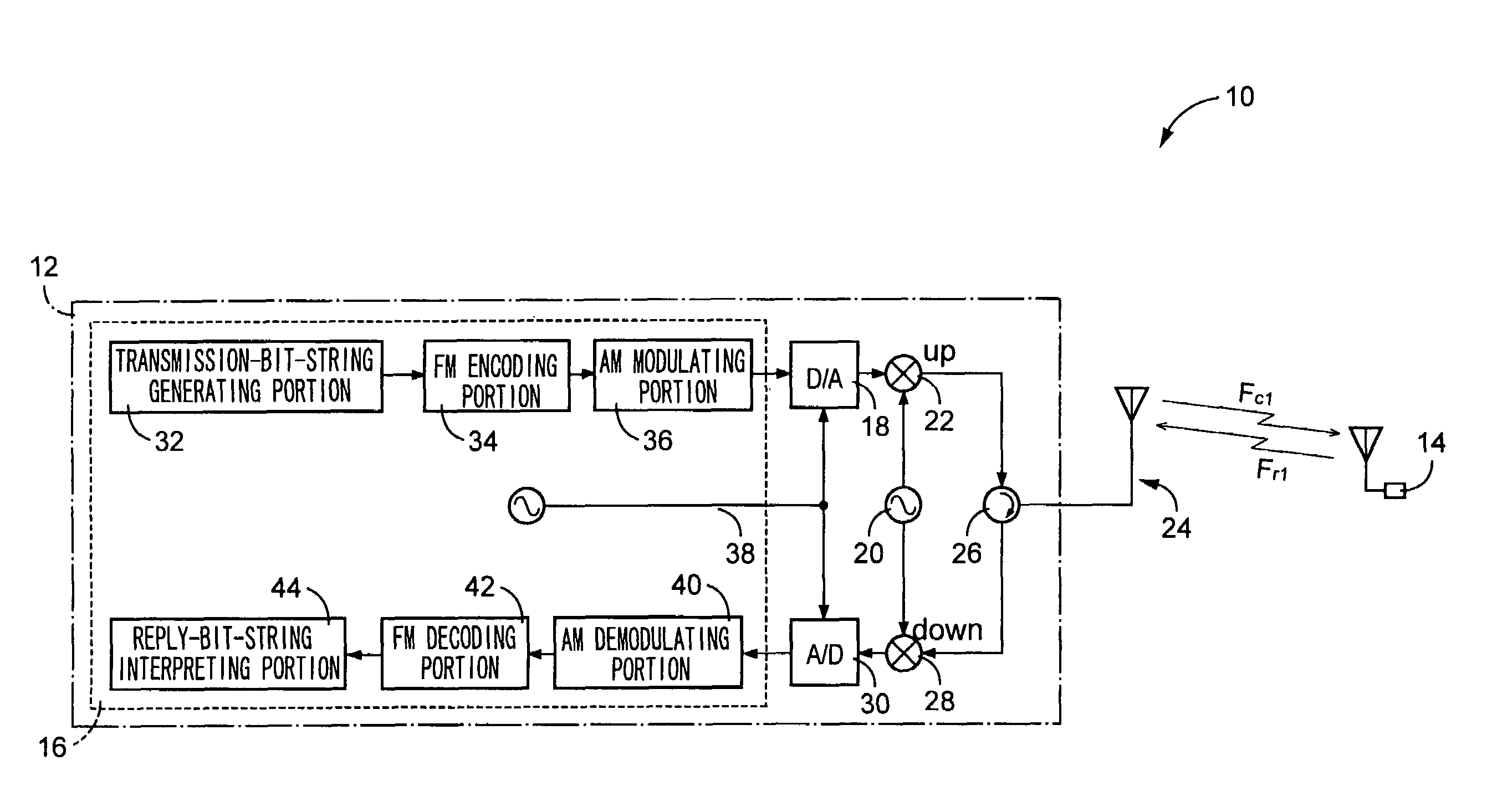
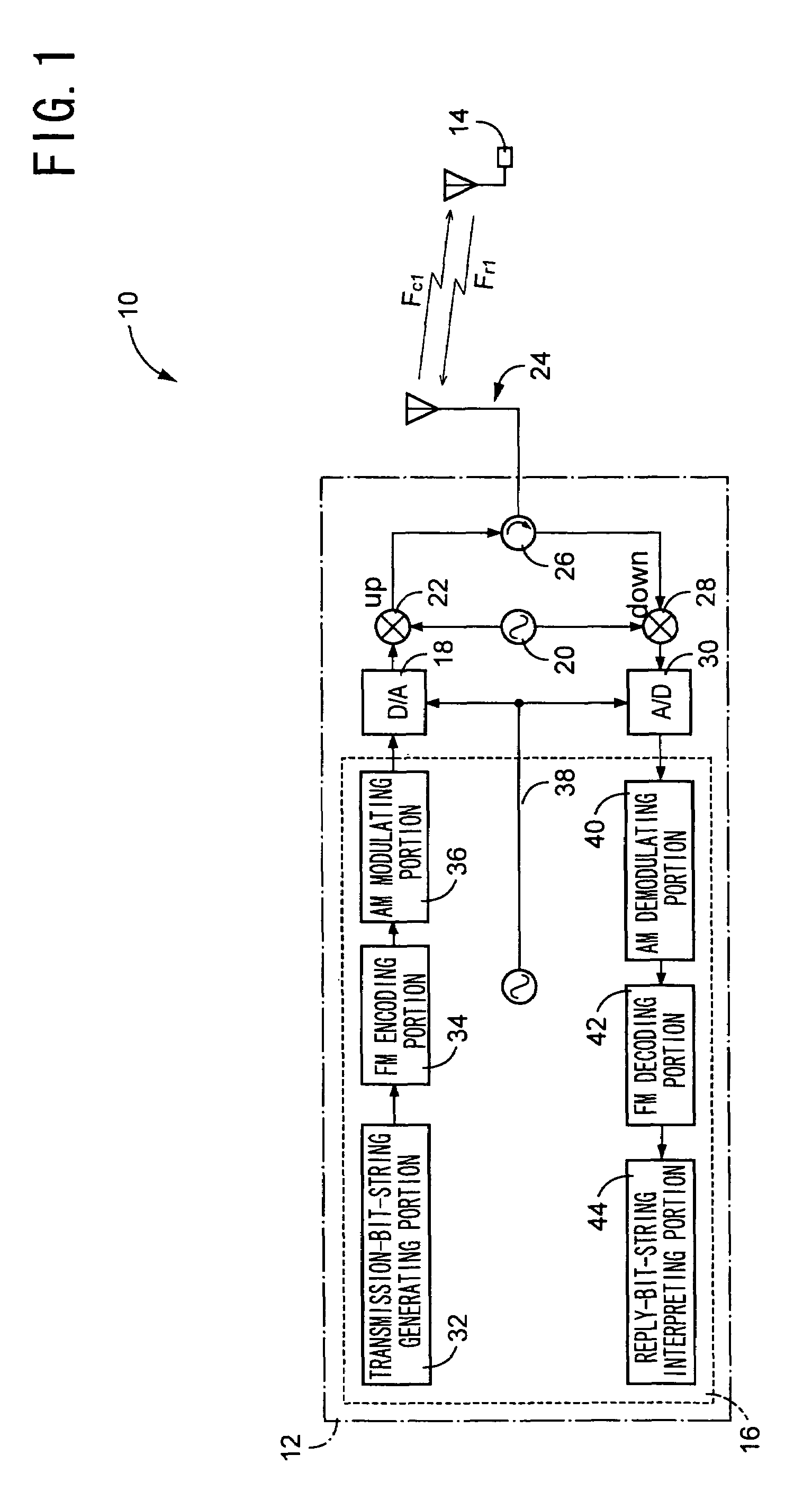
[0041]Referring to FIG. 1, there is shown an arrangement of an ordinary RFID (Radio-Frequency Identification) communication system 10. This RFID communication system 10 includes a radio-frequency identification tag communication device 12 functioning as an interrogator, and a radio-frequency identification tag 14 functioning as a transponder. The radio-frequency identification tag communication device 12 is arranged to transmit a transmission signal in the form of a transmission wave Fc1, and the radio-frequency identification tag 14 is arranged to receive the transmission wave Fc1 and replies to the received transmission wave Fc1 by transmitting a reply signal in the form of a reflected wave Fr1 which is generated by modulating the transmission signal Fc1 on the basis of predetermined information. The radio-frequency identification tag communication device 12 is further arranged to receive the reflected wave Fr1, and demodulate the received reflected wave Fr1. Thus, the radio-frequ...

embodiment 2

[0080]Another preferred embodiment of this invention will be described in detail by reference to the drawings. In the drawing figures referred to in the following description, the same reference signs as used in the preceding embodiment will be used to identify the same elements, redundant description of which is not provided.

[0081]Referring to FIG. 17, there is shown an electric arrangement of a radio-frequency identification tag communication device 90 according to the second embodiment of this invention. This radio-frequency identification tag communication device 90 includes: an Am modulating portion 36 arranged to modulate the encoded signal encoded by the FM encoding portion 34, according to an AM method, on the basis of predetermined information; a transmission-signal D / A converting portion 18 arranged to covert the digital transmission signal generated by the AM modulating portion 36; a plurality of transmitter variable phase shifters 92a, 92b, 92c (hereinafter collectively ...


PUM


Abstract

A radio-frequency identification tag communication device including a BFA weight-value setting portion operable to control a directivity of a transmitter antenna, and an adaptive processing portion operable to implement an adaptive control of a weight to be given to a received signal received by each of a plurality of antenna elements, on the basis of a reply signal transmitted from a radio-frequency identification tag, so that the directivity of the transmitter antenna is changed to a direction in which the frequency identification tag in question is expected to exist, and the weight to be given to each received signal is subjected to the adaptive control, whereby the sensitivity of communication of the communication device with the radio-frequency identification tag is improved.

Description

BACKGROUND OF THE INVENTION[0001]1. Field of the Invention[0002]The present invention relates to an improvement of a radio-frequency identification tag communication device capable of radio communication with radio-frequency identification tags for writing and reading information on and from the radio-frequency identification tags.[0003]2. Discussion of the Related Art[0004]There is known an RFID (Radio-Frequency Identification) communication system wherein a radio-frequency identification tag communication device (interrogator) reads out information, in a non-contact fashion, from small radio-frequency identification tags (transponders) on which desired information is written. In this RFID communication system, the radio-frequency identification tag communication device is capable of reading out the information from the radio-frequency identification tags, even where the radio-frequency identification tags are contaminated or located at positions invisible from the radio-frequency ...

Claims


Application Information

Patent Timeline
Patent Type & Authority Patents(United States)
IPC IPC(8): G08B13/14G06K17/00H01Q1/22H01Q3/26H04B1/59H04B5/02H04B7/06H04B7/08
CPCH01Q1/2216H04B7/0851H04B7/0619H01Q3/26
Inventor KIYOHARA, YUJI
Owner BROTHER KOGYO KK
Why Eureka
Try Eureka