Ramming equipment and ramming construction technology for reducing wall resistance of rammed pipes

A technology of pipe wall resistance and construction technology, which is used in mechanical equipment, pipeline laying and maintenance, pipes/pipe joints/fittings, etc., which can solve the problem that the front end of the casing is difficult to obtain propulsion energy, the utilization efficiency of ramming force is low, and the pipe body is effective. Low energy and other problems, to achieve the effect of reducing the performance of the tamper and the transition dependence of the pipe material, reducing equipment consumption and the cost of pipe purchase, and reducing the coefficient of friction

Active Publication Date: 2021-12-03
SICHUAN GASOLINEEUM CONSTR ENG
View PDF8 Cites 0 Cited by
  • Summary
  • Abstract
  • Description
  • Claims
  • Application Information

AI Technical Summary

Problems solved by technology

Because the single impact time of the rammer is extremely short, according to the momentum theorem F·t=△mv, the effective energy obtained by the pipe body is low, and with the increase of the length of the rammer pipe, the loss of the ramming force along the pipe body It will also gradually increase, and it is difficult for the front end of the casing to obtain effective propulsion energy, which often results in insufficient stamina in the later stage of the rammer
[0004] If the tamping force is increased blindly, in order to prevent the pipe from yielding and deforming, the requirements for the material and wall thickness of the pipe body are higher.
[0005] The utilization efficiency of the output ramming force of the traditional ramming tube is extremely low, and most of the ramming force is used to overcome the resistance of the tube wall to do work, and the effective ramming force actually loaded on the front end is relatively low

Method used


Image

  • Ramming equipment and ramming construction technology for reducing wall resistance of rammed pipes
  • Ramming equipment and ramming construction technology for reducing wall resistance of rammed pipes
  • Ramming equipment and ramming construction technology for reducing wall resistance of rammed pipes

Examples


Embodiment Construction

[0031] Hereinafter, the ramming equipment for reducing the wall resistance of rammed pipes and the ramming construction process thereof according to the present invention will be described in detail with reference to the accompanying drawings and exemplary embodiments. It should be noted that "first", "second", etc. are only for convenience of description and distinction, and cannot be understood as indicating or implying relative importance. "Front", "rear", "left", "right", "inner", "outer" and so on are only for the convenience of describing and constituting a relative orientation or positional relationship, and do not indicate or imply that the referred parts must have the specific Orientation or position.

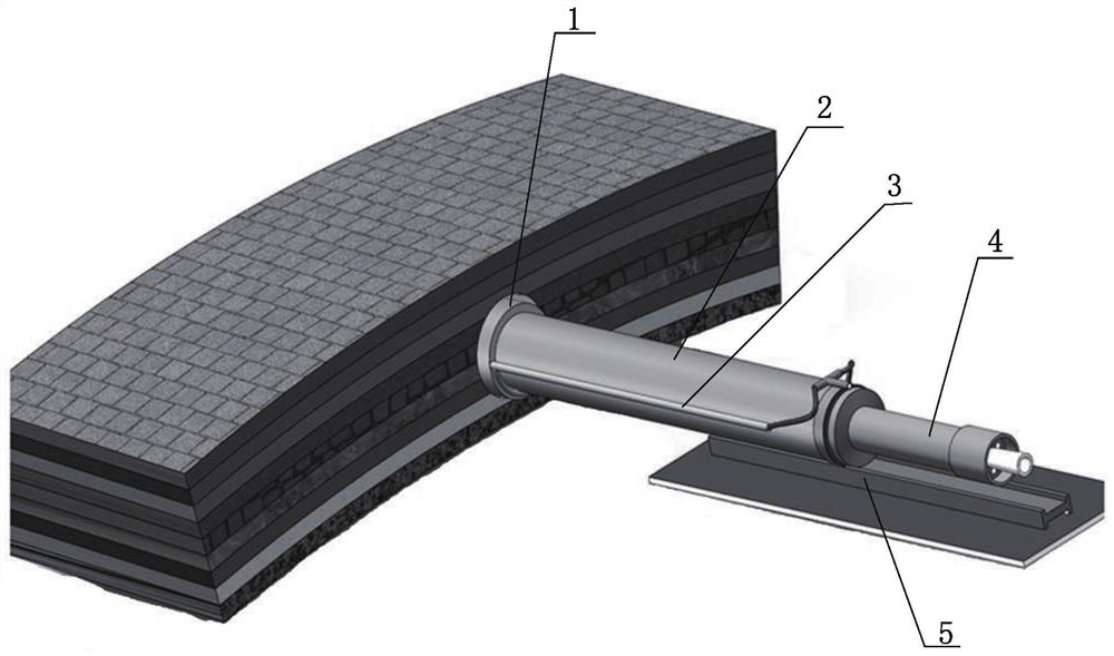
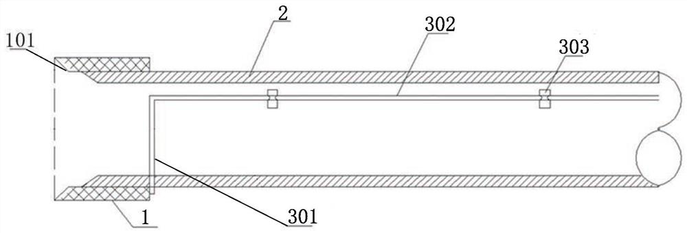
[0032] figure 1 A schematic structural view showing a ramming device for reducing the wall resistance of a rammed pipe according to an exemplary embodiment of the present invention; figure 2 show figure 1 Schematic cross-sectional view of medium steel casing with c...


PUM


Abstract

The invention provides a ramming device for reducing the resistance of the ramming pipe wall and its crossing ramming process. The ramming device for reducing the resistance of the ramming pipe wall includes a cutting ring, a steel casing, and a grouting drag-reducing component , Rammer body and track, wherein, the track is fixedly arranged on the ground for the steel casing to ram into the stratum to be cut along a predetermined direction on the track; the cutting ring is fixedly arranged at the front end of the steel casing, and the cutting ring is not connected with the One end of the steel casing connection is provided with a groove for cutting the soil, and the diameter of the cutting ring is larger than that of the steel casing so that an annular space is formed between the steel casing wall and the cut formation; the rammer and the steel casing The other end is connected to the other end of the steel casing and can exert a ramming force on the steel casing; the grouting drag-reducing component is arranged in the annulus on the outer wall of the steel casing and can pump mud into the annulus to reduce the contact between the outer wall of the steel casing and the Frictional resistance between cutting formations. The invention has the advantages of being able to greatly reduce the resistance during the pipe ramming process, reduce the loss of ramming force, and the like.

Description

technical field [0001] The invention relates to the technical field of shale reservoir development, in particular to a ramming device and a ramming construction process for reducing the wall resistance of a rammed pipe. Background technique [0002] Pipe ramming is a technique in which pipe ramming hammers are used to directly ram the steel pipe to be laid into the ground along the designed route to realize trenchless pipe laying. The working principle is that the large impact force generated by the rammer under the drive of compressed air directly acts on the rear end of the steel pipe, and the steel pipe as a whole overcomes the friction force and shear force between the soil layer and the pipe body, and is forced to cut into the soil. In the crossing construction, it is a practical and effective direct pipe-laying process. At the same time, it can also play an important role in providing protection for ground structures, isolating pebble layers to assist hole formation, a...

Claims


Application Information

Patent Timeline
Patent Type & Authority Patents(China)
IPC IPC(8): F16L1/028F16L1/06
CPCF16L1/028F16L1/06
Inventor 邱德璟张杰
Owner SICHUAN GASOLINEEUM CONSTR ENG
Why Eureka
Try Eureka