Low Noise Generator for Frequency Sweep Signals

A signal generator and signal generation technology, applied in the direction of instruments, utilization of re-radiation, specific array feeding systems, etc., can solve problems such as radar desensitization, improve signal strength, avoid near-carrier phase noise, and simplify filter layout Effect

Active Publication Date: 2016-04-27
QINETIQ LTD
View PDF3 Cites 0 Cited by
  • Summary
  • Abstract
  • Description
  • Claims
  • Application Information

AI Technical Summary

Problems solved by technology

However, phase noise on the LO output can cause the problems mentioned above and lead to radar desensitization

Method used


Image

  • Low Noise Generator for Frequency Sweep Signals
  • Low Noise Generator for Frequency Sweep Signals
  • Low Noise Generator for Frequency Sweep Signals

Examples


Embodiment Construction

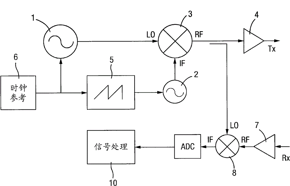
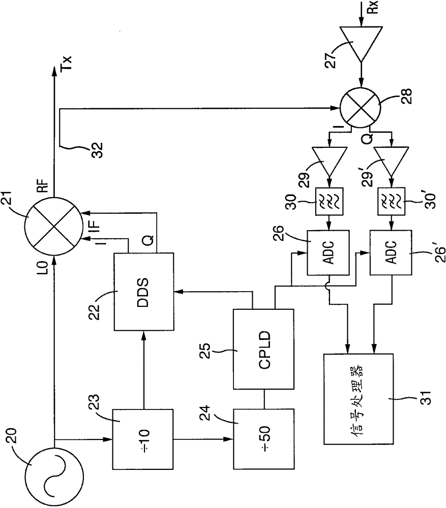
[0038] figure 2 A first embodiment of the present invention is shown. The figure shows a portion of a simplified block diagram of an FMCW radar system. An FRO serving as a local oscillator (LO) 20 operable at 9.2 GHz provides an input to a quadrature up-conversion mixer 21 . The second input to the mixer 21 comes from an IF oscillator in the form of a Direct Digital Synthesizer (DDS) device 22, which in this case is implemented using a pair of Analog Devices AD9858DDS chips. In addition to providing an input to mixer 21 , the output of LO 20 feeds a first frequency divider 23 which in turn drives a second frequency divider 24 . The output of the first frequency divider 23 is used as a reference clock source for the direct digital synthesizer 22 . A second frequency divider 24 provides a clock reference source to a complex programmable logic device (CPLD) 25, which has an output connected to both a DDS and an analog-to-digital converter (ADC) 26, 26' for Digitizes incoming...


PUM


Abstract

A signal generation system suitable for use in a radar system comprising: a local oscillator (LO) and an intermediate frequency IF oscillator, wherein the IF oscillator is a direct digital synthesizer and the LO is not itself locked to another Oscillator's free running oscillator, but the LO is used as the clock reference for the DDS and is the highest frequency oscillator in the system. This LO can also be used as a reference for the digitizer in the receive chain. The present invention takes advantage of the phase noise advantages of free-running oscillators at a distance from the carrier while maintaining coherence with other system components. This system is typically used in FMCW radars.

Description

technical field [0001] The present invention relates to signal generating systems such as may generally be used in radar systems. In particular, the present invention relates to radar systems, especially FMCW (Frequency Modulated Continuous Wave) radar systems, in which it is advantageous to keep the phase noise generated in critical system components as low as possible in order to obtain improved operational performance, both practically and economically . Background technique [0002] FMCW radar systems are characterized by having transmit and receive functions acting simultaneously. This can lead to problems not encountered in more traditional pulsed radars, where the signal may often "leak" from the transmitter to the receiver via the corresponding antenna, making the It is more difficult to detect the signal received from the target. This problem is ameliorated by designing the transmit and receive antennas and associated subsystems such that there is greater isolati...

Claims


Application Information

Patent Timeline
Patent Type & Authority Patents(China)
IPC IPC(8): H03B23/00
CPCG01S7/023G01S7/352H01Q1/3233H01Q21/0031H01Q21/065H01Q25/008H03B23/00G01S7/0232G01S7/0236H01Q13/206G01S13/34
Inventor P·D·L·比斯利
Owner QINETIQ LTD
Why Eureka
Try Eureka