
Acoustic device for use on office partitions

a technology for acoustic devices and partitions, which is applied in the direction of walls, flooring, construction, etc., can solve the problems of intruding into the space of cubicles, less stable, etc., and achieve the effects of improving the acoustical efficacy of partitions, convenient installation, and low manufacturing cos

Inactive Publication Date: 2009-08-18
STARK CHARLES H
View PDF8 Cites 3 Cited by
  • Summary
  • Abstract
  • Description
  • Claims
  • Application Information

AI Technical Summary

Benefits of technology

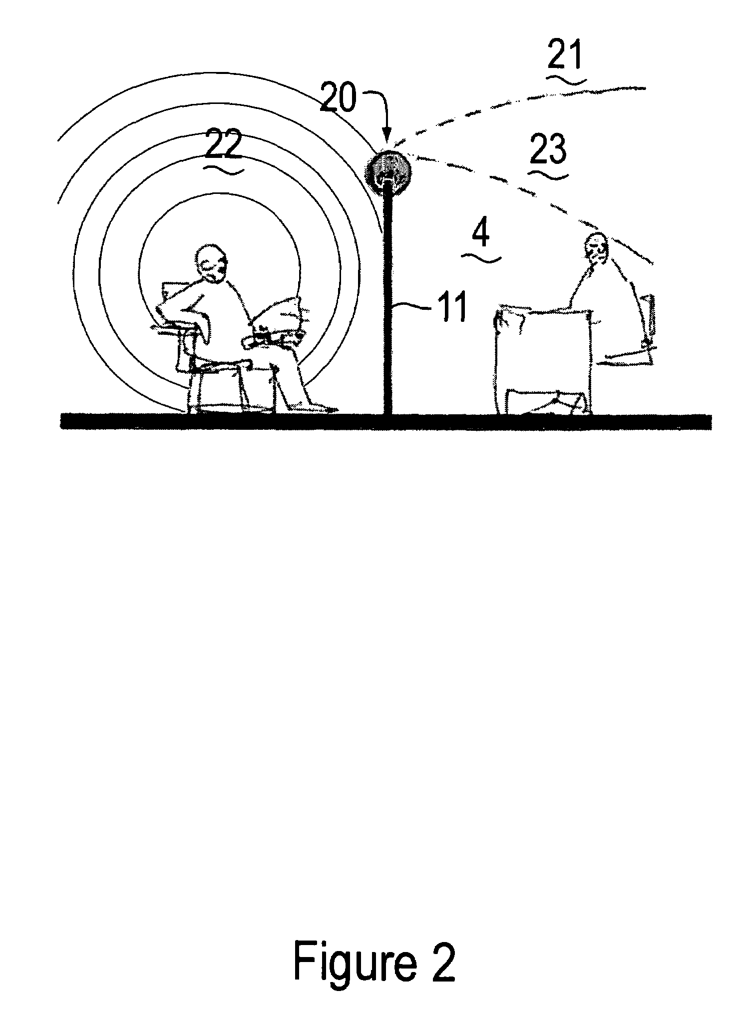
[0003]This invention consists of a device that is mounted on the top of a movable office partition to improve the acoustical efficacy of the partition. It is equally effective on new or on existing partitions and can be made to fit all the major brands in the movable partition market; It is attractive, lightweight, durable, inexpensive to manufacture and easy to install. The device is able to absorb incident sound and redirect diffracted sound to a path that will reduce sound levels reaching a listener in he next cubicle.
[0006]The core is wrapped with a fiberglass or other similar absorbent material. The absorbent material should consist of two or more layers of varying densities and thickness to create the most effective absorption coefficient. An example of a good combination is an outer layer of ⅛″, thick fiberglass having a density of 6 pounds per cubic foot covering a 1″, thick layer of fiberglass having a density of 3 pounds per cubic foot over a ⅞″, thick layer of fiberglass having a density of 4 pounds per cubic foot. The overall diameter would then be 1″-0″ (4″ of absorbent material and an 8″ core.) This is about the ideal diameter because it would absorb and refract sound frequencies above 1000 Hz and diffract sound frequencies below 1000 Hz. Larger sizes would be acoustically slightly more effective, but would be less stable and intrude into the space of a cubicle. Smaller sizes would be acoustically less functional.
[0007]The surface material would consist of an acoustically transparent woven fabric. Materials are available from various manufacturers that provide the correct acoustical properties, do not sag or “puddle,” are durable, have a low cost and come in many colors. These are the ideal characteristics for the covering of the diffraction abatement invention because they would match the companion partitions in color and texture.
[0008]The fabric should be adhered to a thin acoustical fiberglass backing to provide stability and a surface upon which to glue the fabric to the fiberglass sound absorbent material. An acceptable alternate method of attachment is to tightly wrap the fabric around the sound absorbent material and staple or otherwise mechanically attach it. In either case the fabric would be cut to fit and folded over the ends of the sound absorbent material and attached thereto with glue.
[0010]A corner sound abatement device of similar design is optional at the manufacturer's judgment. The corners would be of the same construction as the linear devices, but would have 45 degree ends cemented together to form a 90 degree corner. The acoustic benefits would be the same.

Problems solved by technology

Larger sizes would be acoustically slightly more effective, but would be less stable and intrude into the space of a cubicle.

Method used


Image

  • Acoustic device for use on office partitions
  • Acoustic device for use on office partitions
  • Acoustic device for use on office partitions

Examples


Embodiment Construction

)

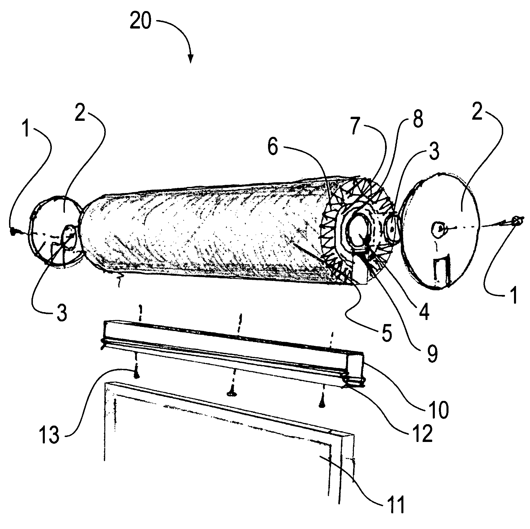
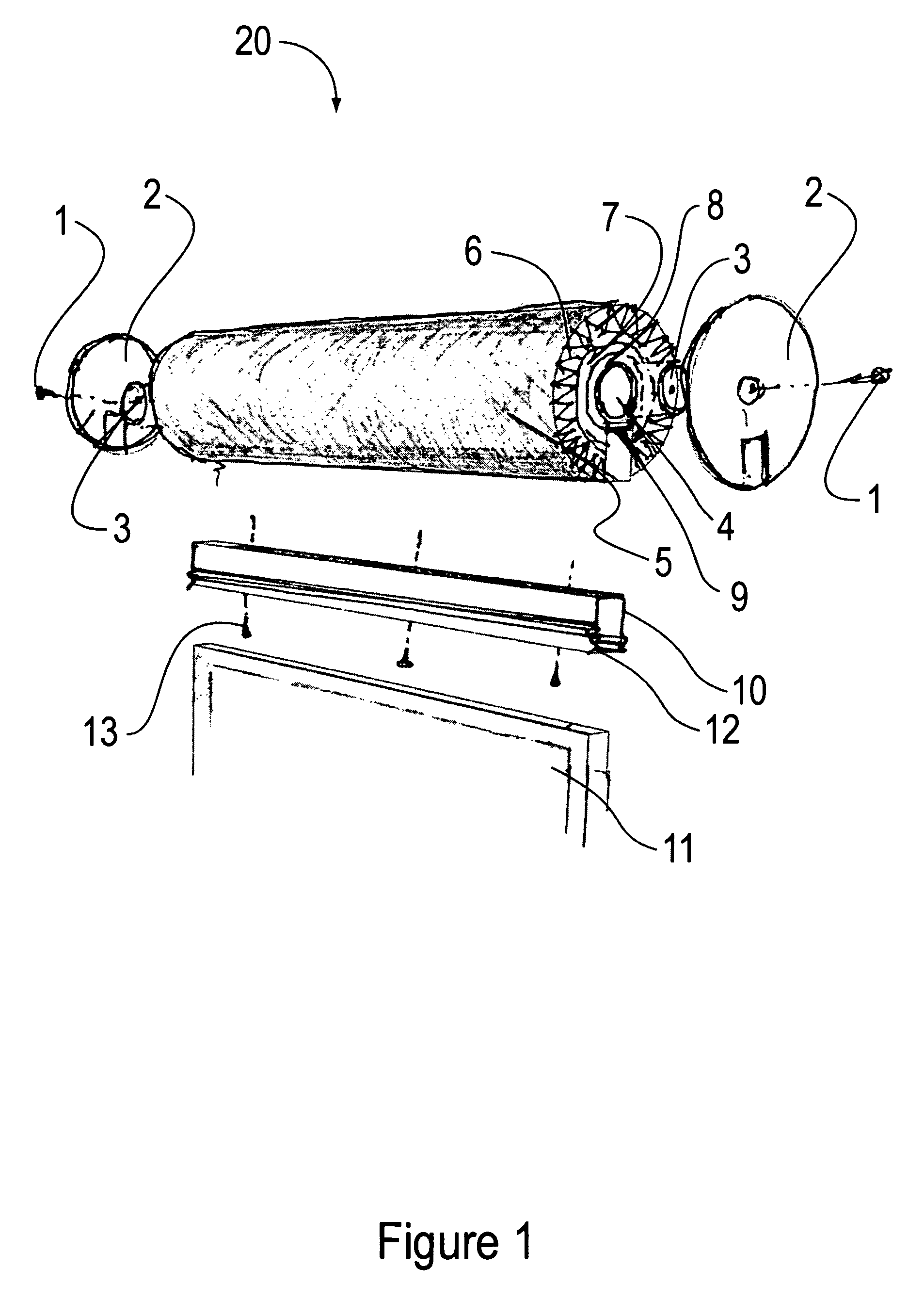
[0013]FIG. 1 is an exploded view showing the components and construction of the sound abatement acoustic device 20. The structural core or septum of the device consists of a length of 8″ diameter pipe 4 which may be plastic, fiberglass or lightweight metal. Attached to the bottom of the core 4 is a core channel 9 that provides a flat mounting surface for the mounting channel 10. Fastened to core channel 9 with adhesive, rivets, or screws 13 is mounting channel 10. Mounting channel 10 is bent with small inward curves at the bottom of each leg 12 which provide a spring action. Wrapped around the pipe core 4 is ⅞″ thick 6# an inner layer 8 of fiberglass having a thickness from about ½″ to about 1″ and a density from about 2 to about 8 pounds per cubic foot. In practice it has been found that an inner layer 8 having a thickness of ⅞″ and a density of 6 pounds per cubic foot works particularly well. There is a gap in the inner layer 8 so that the mounting channel 10 is exposed. Wrapped ...


PUM


Abstract

This invention is a device that is mounted on the top of a movable office partition to improve the acoustical efficacy of the partition. It is equally effective on new or on existing partitions and can be made to fit all the major brands in the movable partition market. It is attractive, lightweight, durable, inexpensive to manufacture and easy to install. The device is able to absorb incident sound and redirect diffracted sound to a path that will reduce sound levels reaching a listener in adjacent cubicles.

Description

CROSS REFERENCE TO RELATED APPLICATIONS[0001]This application claims the benefit of U.S. provisional patent application Ser. No. 60 / 777,885 filed Mar. 1, 2006.BACKGROUND OF THE INVENTION[0002]Low, movable partitions have become the standard method of providing individual space cubicles for millions of office workers throughout the world. The principal deficiency with all low participation systems is the lack of acoustical privacy. If a worker in a cubicle is able to hear what is said in the next cubicle, it may be hard to concentrate and result in the loss of efficiency and productivity. This invention consists of a sound diffraction device to be installed on the top of movable office partitions. The addition of this invention improves the acoustical performance of movable office partitions.SUMMARY OF THE INVENTION[0003]This invention consists of a device that is mounted on the top of a movable office partition to improve the acoustical efficacy of the partition. It is equally effec...

Claims


Application Information

Patent Timeline
Patent Type & Authority Patents(United States)
IPC IPC(8): E04B1/82
CPCE04B1/8209E04B2/7416E04B2002/7418E04B2/7409
Inventor STARK, CHARLES H.
Owner STARK CHARLES H
Learn More