Display device with light guide plate having antireflection portions on light incident surfaces

a technology of light guide plate and display device, which is applied in the direction of lighting device details, lighting and heating equipment, instruments, etc., can solve the problems of reducing the contrast of stereoscopic images or two different images, and achieve the effect of enhancing the contrast of a display imag

Active Publication Date: 2009-08-18
MITSUBISHI ELECTRIC CORP +1
View PDF7 Cites 20 Cited by
  • Summary
  • Abstract
  • Description
  • Claims
  • Application Information

AI Technical Summary

Benefits of technology

[0006]This invention has been made in order to solve the problem as stated above, and provides a display device which can enhance the contrast of stereoscopic image or two different images with uniform luminous intensity distributions maintained.
[0011]According to this invention, antireflection portions are provided at parts other than light transmission portions, whereby reflection light ascribable to the retrocession of light inputted from one end after being reflected from the other end can be reduced, and the contrast of a display image can be enhanced.

Problems solved by technology

This has resulted in the problem that the contrast of the stereoscopic image or two different images lower.

Method used


Image

  • Display device with light guide plate having antireflection portions on light incident surfaces
  • Display device with light guide plate having antireflection portions on light incident surfaces
  • Display device with light guide plate having antireflection portions on light incident surfaces

Examples


embodiment 1

[0032]Hereinafter, an embodiment of the present invention will be described with reference to the drawings. The inventors have found out that, in view of the operating principles of a two-image display, the prevention of reflection from the end face of a light guide plate is an effective expedient as elucidated below.

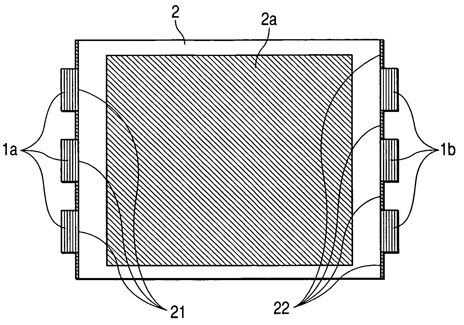
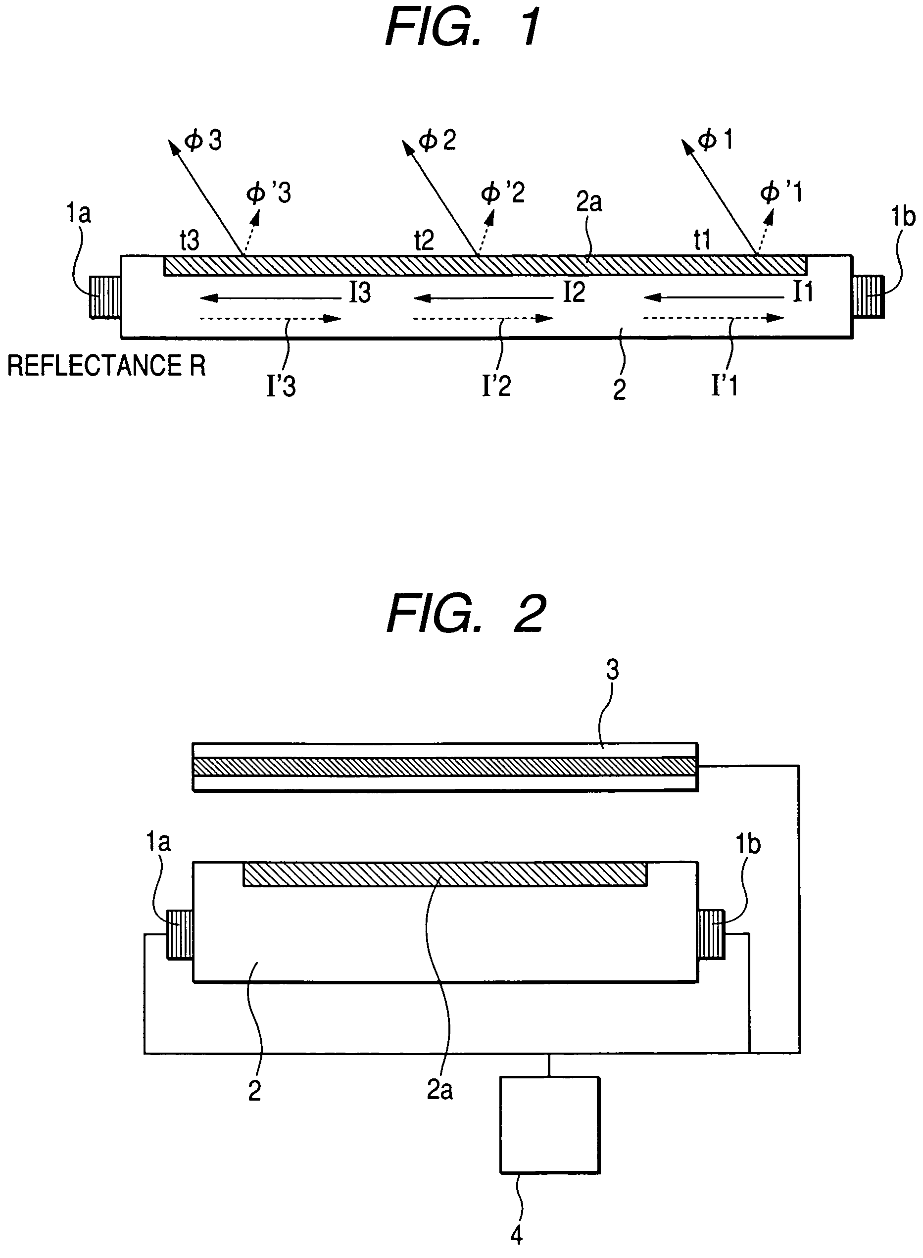
[0033]In a case where light has been inputted from one light source to the light guide plate, the luminance distribution of light emergent from a light extraction portion can be computed as stated below, from the situation of light propagating within the light guide plate, and so on. FIG. 1 is an explanatory diagram for explaining the propagation of light within the light guide plate in a configuration in which a pair of light sources are arranged on the outer sides of both the end faces of the light guide plate 2. Referring to FIG. 1, it is assumed that only the light source 1b of the pair of light sources 1a and 1b is turned ON. I1 denotes the propagation intensity of...

embodiment 2

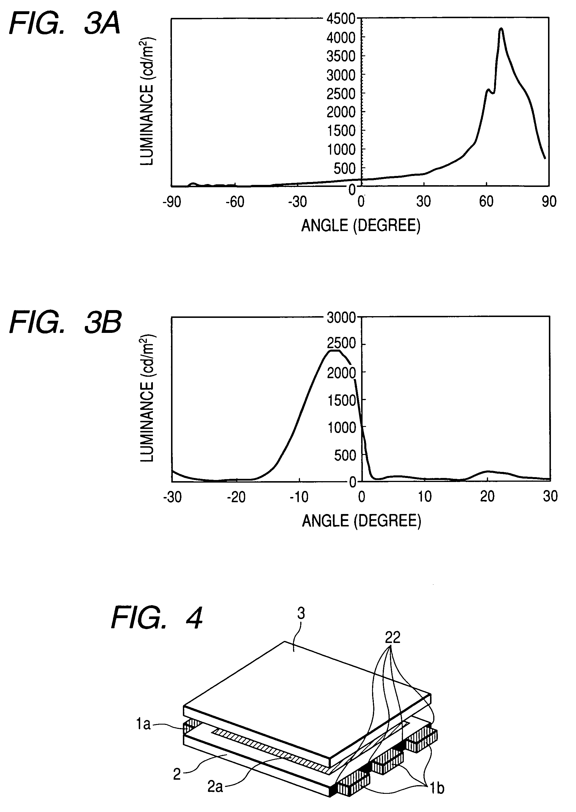
[0043]FIG. 6 is a model diagram for explaining a display device according to Embodiment 2 for carrying out this invention. Referring to FIG. 6, both the end faces of a light guide plate 2 are antireflection portions 22, and hole arrays 23a and 23b are provided inside both the end faces. Pairs of light sources 1a and 1b are such that light emitting diodes (LEDs) are embedded in the hole arrays 23a and 23b, respectively. Lights outputted from the light sources 1a or 1b propagate within the light guide plate 2, and they are extracted onto the side of a transmission type liquid crystal panel 3 from a light extraction portion 2a disposed in the surface of the light guide plate 2. The light extraction portion 2a is constructed by subjecting the surface of the light guide plate 2 to a roughening work so that light having passed through this light extraction portion may have a directionality. When only the light sources 1a are turned ON, a luminous intensity distribution shown in FIG. 3A is...

embodiment 3

[0047]FIG. 9 is a model diagram for explaining a display device in Embodiment 3 for carrying out this invention. As shown in FIG. 9, a light guide plate 2 in this embodiment is constructed of two transparent plates 43 and 44, each of which is such that one of the end faces of the light guide plate is a light transmission portion 45, while the other is an antireflection portion 46. The two transparent plates 43 and 44 are placed one over the other in such a manner that light extraction portions 43a and 44a are held in the same sense, and that the light transmission portions 45 are opposite to each other. Pairs of light sources 1a and 1b are arranged on the outer sides of the light transmission portions 45. The light extraction portion 43a is constructed by subjecting the surface of the transparent plate 43 to a roughening work so that lights emitted from the light sources 1a and guided through this transparent plate 43 may become a luminous intensity distribution as shown in FIG. 3A....


PUM

PropertyMeasurementUnit
angleaaaaaaaaaa
thicknessaaaaaaaaaa
angleaaaaaaaaaa

Abstract

A display device includes a light guide plate which includes a light transmission portion and an antireflection portion at two opposite end faces and which is provided with a light extraction portion in part of a surface, respective light sources which are arranged on outer sides of the two opposite end faces, a transmission liquid crystal panel located adjacent to the light extraction portion, and a synchronous drive unit that alternately turns ON the light sources and that displays an image that is synchronous with an alternating turn-ON operation of the transmission liquid crystal panel.

Description

BACKGROUND OF THE INVENTION[0001]1. Field of the Invention[0002]This invention relates to display devices, and more particularly to a display device which is capable of presenting a stereoscopic display or simultaneously displaying two different images in separate angular directions, and which is used for an information equipment terminal.[0003]2. Description of the Related Art[0004]In a prior-art display device which is capable of stereoscopic display or two-screen display (in which two different images are simultaneously displayed in separate angular directions), a pair of light sources are arranged in the vicinities of both the end faces of a light guide plate whose surface is formed with a light extraction portion having a directionality in the emergent angle of light, by a roughening work or the like, and the light extraction portion is overlaid with a dual-side prism sheet and a transmission type liquid crystal panel, wherein the pair of light sources are alternately turned ON...

Claims


Application Information

Patent Timeline
Patent Type & Authority Patents(United States)
IPC IPC(8): G02F1/1335F21V7/04
CPCG02F1/133615G02F1/1335
Inventor ITO, ATSUSHIYUUKI, AKIMASAZUMOTO, NOBUYUKIYONEDA, TOSHIYUKISASAGAWA, TOMOHIRO
Owner MITSUBISHI ELECTRIC CORP
Why Eureka
Try Eureka