Shielding function for magnetic head in magnetic disk device

a magnetic disk and shielding function technology, applied in the field of magnetic disk devices, can solve the problems of limited size of magnetic disk devices of this kind, serious hindrance to realizing a magnetic disk device of the vertical recording system, and the expansion of the external size of the magnetic shielding member, so as to improve the shielding function of the magnetic head

Inactive Publication Date: 2009-08-18
WESTERN DIGITAL TECH INC
View PDF6 Cites 1 Cited by
  • Summary
  • Abstract
  • Description
  • Claims
  • Application Information

AI Technical Summary

Benefits of technology

[0013]It is a feature of the present invention to provide a magnetic disk device capable of improving the shielding function for the magnetic head yet maintaining a form factor.

Problems solved by technology

According to the prior art 1, however, a problem exists in that the magnetic shielding member is provided on the housing separated away from the magnetic head and, hence, the shielding function is not fully exhibited and, further, the external size increases by the size of the magnetic shielding member.
However, limitation has been imposed on the size of the magnetic disk device of this kind such as of the 2.5-type (mobile type) and the 3.5-type, and it is important that the predetermined size (form factor) is not exceeded even when the magnetic shielding function is imparted.
In the magnetic disk devices for a mobile use mounted on the notebook personal computers and on the portable data terminals, in particular, very strict requirements or limitations are imposed on decreasing the thickness, and difficulty is involved in employing a structure that has an increased thickness relative to the currently employed magnetic disk devices, causing a serious hindrance to realizing a magnetic disk device of the vertical recording system.
According to the prior art 2, there is a problem that the magnetic shielding member is provided on only the base portion and the cover portion that face the magnetic head, making it difficult to exhibit the shielding function to a sufficient degree.
According to the prior art 3 or 4, the magnetic shielding members are provided by the sides of the magnetic head, leading to a problem in that the shielding function is not exhibited to a sufficient degree.

Method used


Image

  • Shielding function for magnetic head in magnetic disk device
  • Shielding function for magnetic head in magnetic disk device
  • Shielding function for magnetic head in magnetic disk device

Examples


first embodiment

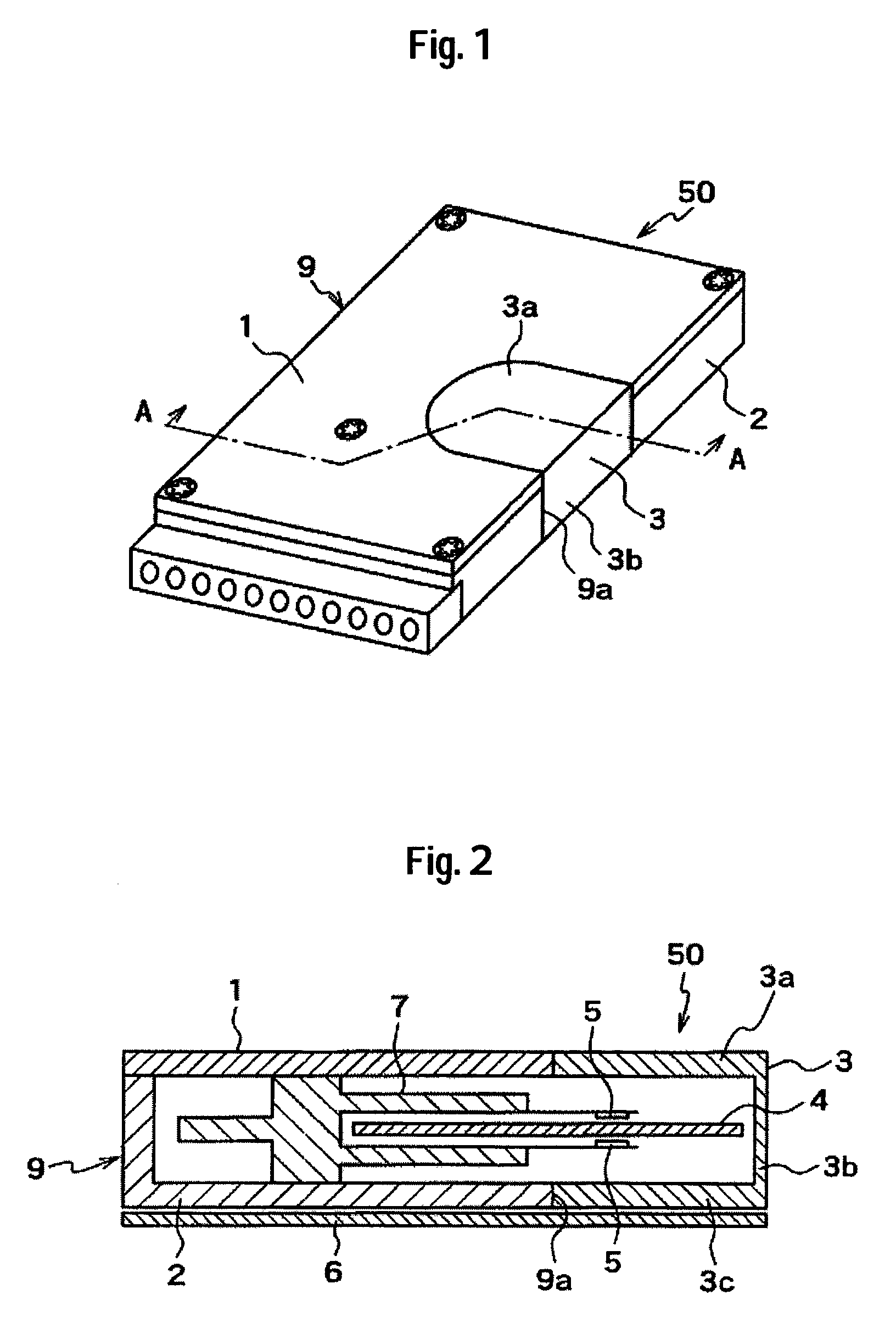
[0038]First, a magnetic disk device of a first embodiment of the invention will now be described with reference to FIGS. 1 and 2. FIG. 1 is a perspective view illustrating the magnetic disk device according to the first embodiment of the invention, and FIG. 2 is a sectional view along A-A in FIG. 1.

[0039]The magnetic disk device 50 includes a rotary disk-type magnetic disk 4, a magnetic head 5 for recording information into the magnetic disk and for reproducing information from the magnetic disk, a magnetic disk drive mechanism 7 for supporting the magnetic head 5 and for moving the magnetic head 5 in the radial direction of the magnetic disk 4, a housing 9 constituted by a base 2 made of a nonmagnetic material and a cover 1 made of a nonmagnetic material, a magnetic shielding member 3 made of a magnetic material, and a circuit board 6 for controlling the magnetic disk device 50.

[0040]The magnetic disk 4 is constituted by a rotary disk-type magnetic disk with which information is re...

second embodiment

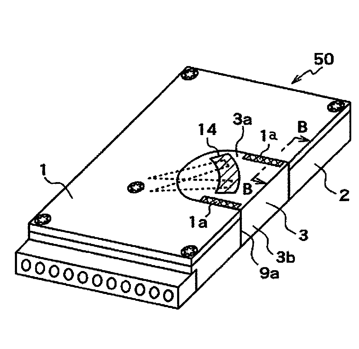
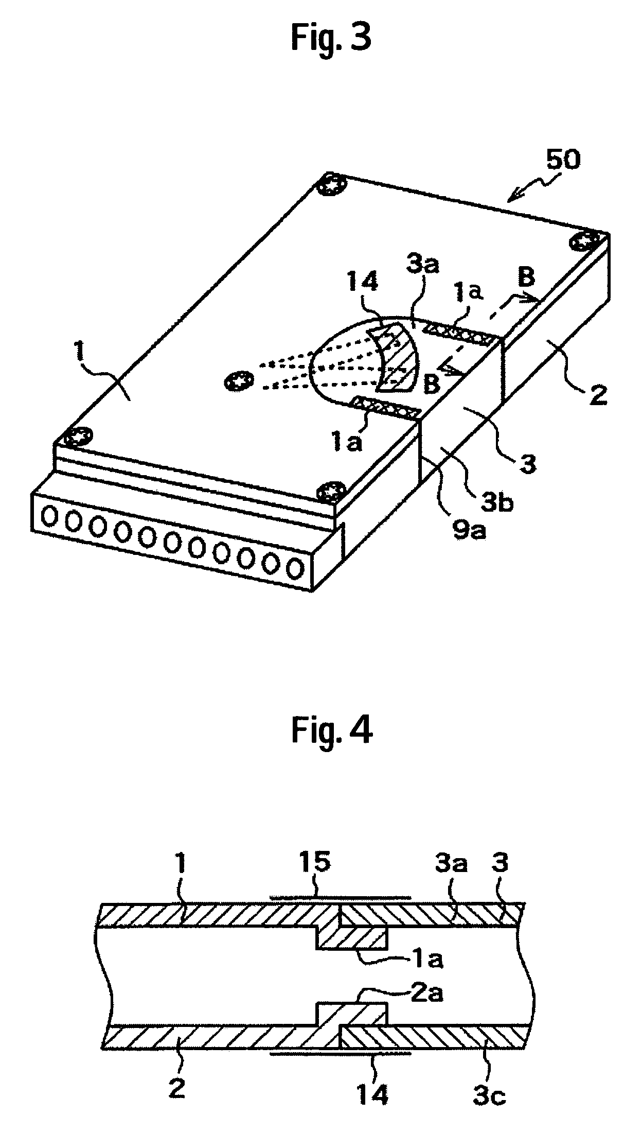
[0048]A second embodiment of the invention will be described next with reference toFIGS. 3 and 4. FIG. 3 is a perspective view of the magnetic disk device according to the second embodiment of the invention, and FIG. 4 is a sectional view along B-B in FIG. 3. The second embodiment is different from the first embodiment with respect to a point described below. In other respects, however, the second embodiment is basically the same as the first embodiment.

[0049]In the second embodiment, the upper wall portion 3a of the magnetic shielding member 3 is brought into contact with the engaging step 1a of the upper wall portion (cover 1) of the housing 9, and the bottom wall portion 3c of the magnetic shielding member 3 is brought into contact with the engaging step 2a of the bottom wall portion (bottom wall portion of the base 2) of the housing 9 in a manner of being overlapped thereon, and the magnetic shielding member 3 is disposed in the cut-away portion 9a. Due to these engaging steps 1...

third embodiment

[0052]A third embodiment of the invention will be described next with reference to FIGS. 5 to 7. FIG. 5 is a perspective view of the magnetic disk device according to the third embodiment of the invention, FIG. 6 is a sectional view along C-C in FIG. 5, and FIG. 7 is a perspective view illustrating a method of producing the cover 1 used in the third embodiment. Here, FIG. 6 does not show the parts in the housing. The third embodiment is different from the first embodiment with respect to a point described below. In other respects, however, the third embodiment is basically the same as the first embodiment.

[0053]In the third embodiment, the cover 1 is made of a magnetic material, the base 2 is made of a nonmagnetic material, and the circuit board 6 has a silicon steel plate core. A buffer member 25 is arranged between the circuit board 6 and the base 2. The cover 1 is provided with a tongue portion 1b extending from one side thereof. The tongue portion 1b is vertically folded downwar...


PUM


Abstract

Embodiments of the invention provide a magnetic disk device capable of improving the shielding function for the magnetic head yet maintaining a form factor. In one embodiment, a magnetic disk device comprises a magnetic disk; a magnetic head for recording / reproducing information; a magnetic disk drive mechanism for moving magnetic head in the radial direction of the magnetic disk; a housing including a base and a cover having a nonmagnetic material; and a magnetic shielding member having a magnetic material. The housing has a cut-away portion corresponding to a range in which the magnetic head moves, and the magnetic shielding member is formed in a U-shape including an upper wall portion, a side wall portion and a bottom wall portion. The magnetic shielding member covers the range in which the magnetic head moves, and is disposed in the cut-away portion so as to form substantially the same surface as the surfaces of the upper wall, side wall and bottom wall of the housing.

Description

CROSS-REFERENCES TO RELATED APPLICATIONS[0001]This application claims priority from Japanese Patent Application No. JP2004-289705, filed Oct. 1, 2004, the entire disclosure of which is incorporated herein by reference.BACKGROUND OF THE INVENTION[0002]This invention relates to a magnetic disk device and, particularly, to a magnetic disk device for recording information into magnetic disks relying upon a vertical magnetic recording system.[0003]In the magnetic disk devices in recent years, attempts have been made to improve the conventional longitudinal magnetic recording system and to develop a vertical magnetic recording system in an effort to increase the recording density.[0004]A magnetic disk device which is based upon the vertical magnetic recording system, generally, uses a single magnetic pole head and a magnetic disk medium of a two-layer structure. In this magnetic disk device, the single magnetic pole head works to concentrate the external disturbing magnetic field entering...

Claims


Application Information

Patent Timeline
Patent Type & Authority Patents(United States)
IPC IPC(8): G11B5/012
CPCG11B5/10
Inventor EGUCHI, TAKEHIKOSHIMIZU, TOSHIHIKOTOKUYAMA, MIKIO
Owner WESTERN DIGITAL TECH INC
Why Eureka
Try Eureka