Resin molded body, receiving jig and method for manufacturing push button switch member

a technology of resin molded body and push button switch, which is applied in the direction of manufacturing tools, other domestic articles, contacts, etc., can solve the problems of undeveloped efficient method for separating overlap gates and resin molded parts, and troublesome key operation, so as to improve working efficiency, transmission efficiency, and easy separation

Inactive Publication Date: 2009-09-08
SHIN-ETSU POLYMER CO LTD
View PDF4 Cites 2 Cited by
  • Summary
  • Abstract
  • Description
  • Claims
  • Application Information

AI Technical Summary

Benefits of technology

[0009]It is an object of the present invention to easily separate resin molded parts which are used for a push button switch member with less light leakage from the side faces and less trouble in key operation.

Problems solved by technology

In case of using the front parts manufactured from the resin molded body having the side gates, a part of the gates is remained and causes a trouble in key operation.
However, an efficient method for separating the overlap gates and the resin molded parts have not been developed yet, and there is a need of an easy method for separating resin molded parts from the resin molded body in a short time.

Method used


Image

  • Resin molded body, receiving jig and method for manufacturing push button switch member
  • Resin molded body, receiving jig and method for manufacturing push button switch member
  • Resin molded body, receiving jig and method for manufacturing push button switch member

Examples


first embodiment

of the Present Invention

[0055]Hereinafter, a first embodiment of the present invention will be described with referent to the drawings.

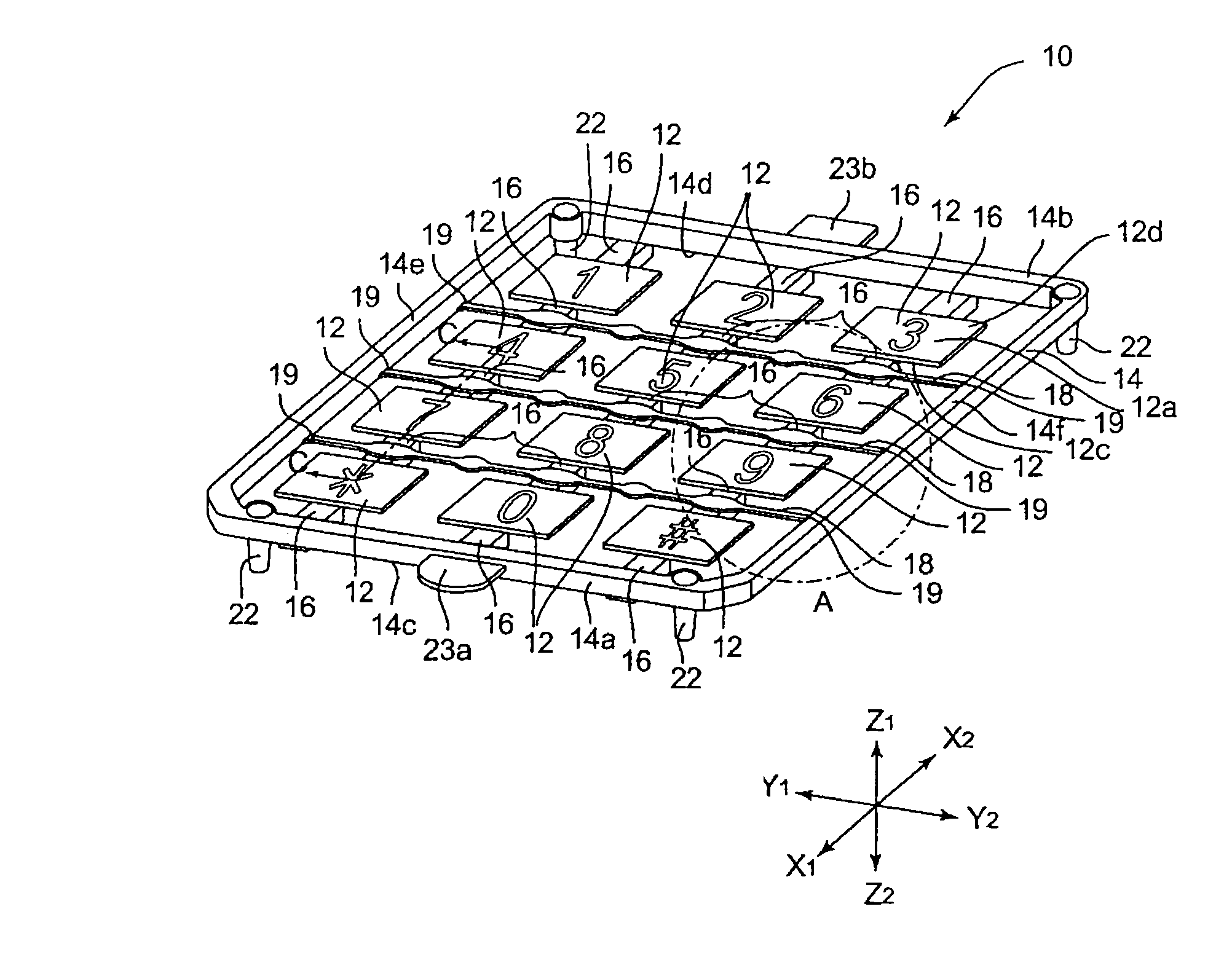
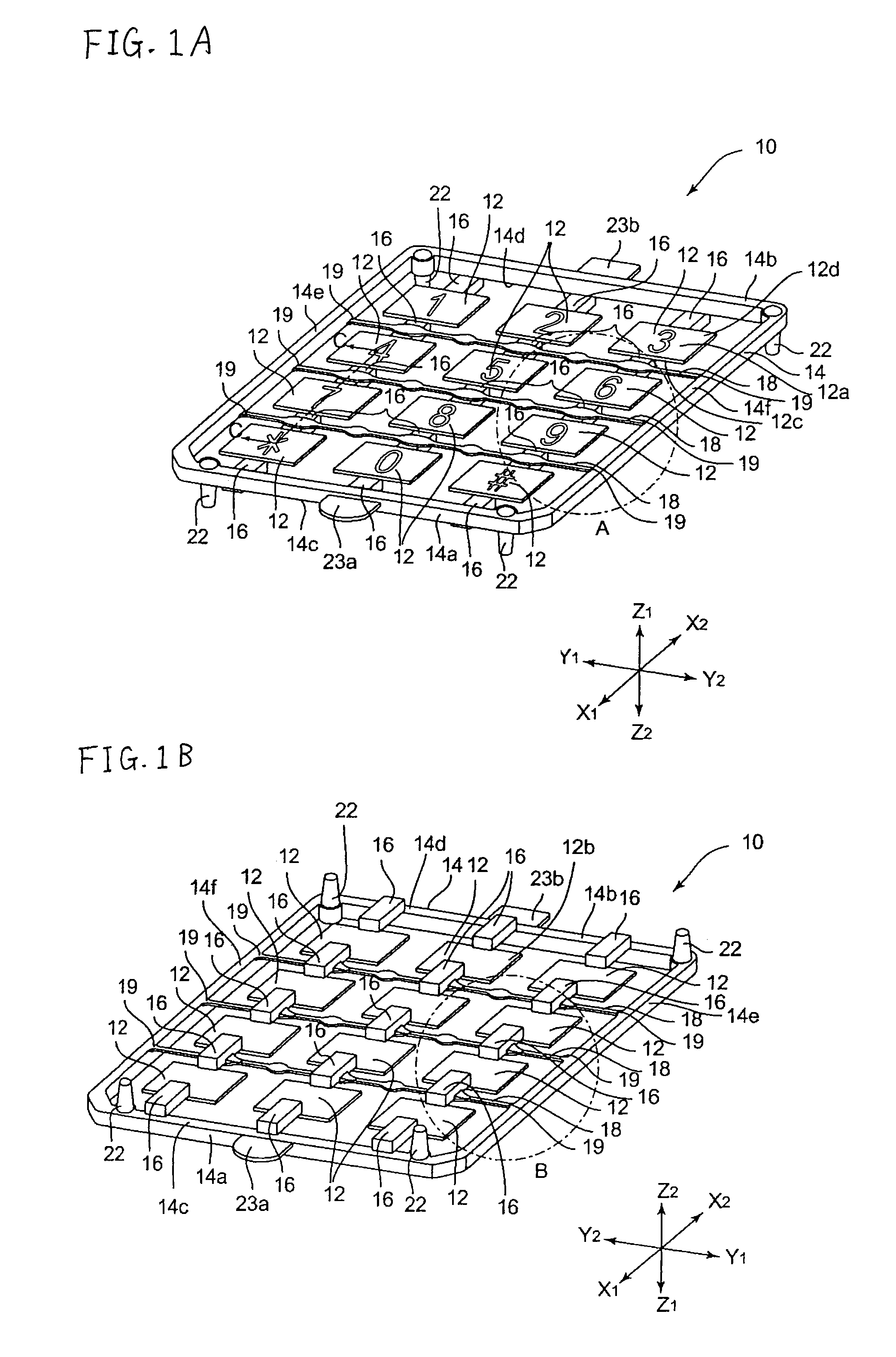
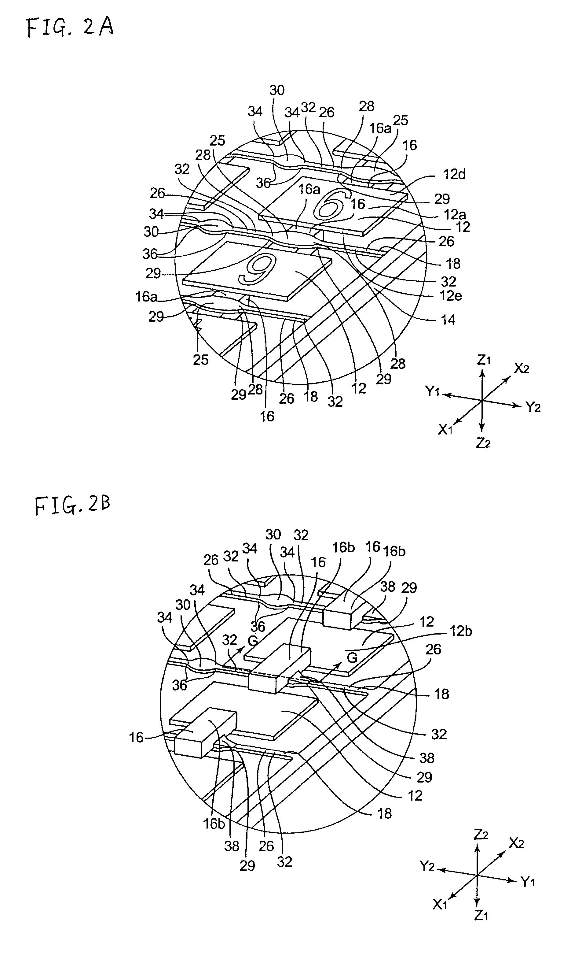
[0056]FIG. 1A shows a perspective view from the front side illustrating configuration of the resin molded body 10 according to the first embodiment. FIG. 1B shows a perspective view from the back face illustrating configuration of the resin molded body 10 according to the first embodiment. FIG. 2A shows an enlarged view of a portion surrounded by a dashed-dotted line A in FIG. 1A. FIG. 2B shows an enlarged view of a portion surrounded by a dashed-dotted line B in FIG. 1B. FIG. 3 shows a cross sectional view of the resin molded body 10 according to the first embodiment along the line C-C in FIG. 1A. FIG. 4 shows a cross sectional view of the resin molded body 10 according to the first embodiment along the line G-G line in FIG. 2B.

[0057]As shown in FIGS. 1A and 1B, the resin molded body 10 comprises twelve resin molded parts 12 (hereinafter referred to...

second embodiment

of the Present Invention

[0090]Hereinafter, a resin molded body 70 according to a second embodiment of the present invention will be described with referent to the drawings. In the following description about resin molded body 70 according to the second embodiment, some of common portions to the first embodiment are given the same numerals and the description of the common portions will be omitted or simplified.

[0091]FIG. 11A shows a perspective view from the front side illustrating configuration of the resin molded body 70 according to the second embodiment. FIG. 11B shows a perspective view from the back side illustrating configuration of the resin molded body 70 according to the second embodiment. FIG. 12A shows an enlarged view of a portion surrounded by a dashed-dotted line E in FIG. 11A. FIG. 12B shows an enlarged view of a portion surrounded by a dashed-dotted line F in FIG. 11B.

[0092]As shown in FIGS. 11A and 11B, the resin molded body 70 mainly comprises twelve parts 12, a f...


PUM

PropertyMeasurementUnit
lengthaaaaaaaaaa
curvature radiusaaaaaaaaaa
widthaaaaaaaaaa

Abstract

To separate resin molded parts that are used for a push button switch member with less light leakage from the side faces and less trouble in key operation, easily, a resin molded body comprises one or more resin molded parts for a push button switch member, a frame surrounding the outside of the resin molded parts, one or more gates connecting a plurality of the resin molded parts each other or the resin molded part to the frame and one or more runners crossing the longitudinal direction of the gates, wherein the gates are connected at the back faces of the resin molded parts not to be coated with light shielding paint, and wherein the runners are connected to the gates on the same surfaces as the resin molded parts are connected to and are connecting the opposing sides of the frame.

Description

CLAIM OF PRIORITY[0001]The present invention contains subject matter related to and claims the benefit of Japanese Patent Application No. 2006-250850, filed in the Japan Patent Office on Sep. 15, 2006, the entire contents of which being incorporated herein by reference.BACKGROUND OF THE INVENTION[0002]The present inventions relate to a resin molded body, its receiving jig and a method for manufacturing a push button switch member using the resin molded body and the receiving jig.[0003]In a conventional method, a plurality of resin molded parts has been manufactured by processes comprised of: (i) a process for forming a resin molded body, wherein the resin molded body comprises a plurality of resin molded parts connected at its side faces each other by gates (hereinafter called “side gates”); and (ii) a process for separating the resin molded parts from the side gates of the resin molded body.[0004]For example, Japanese Patent Laid-Open Publication No. H08-183072 discloses a resin mo...

Claims


Application Information

Patent Timeline
Patent Type & Authority Patents(United States)
IPC IPC(8): H01H1/10
CPCB29C45/0055B29C45/382H01H13/705H01H13/88B29C2045/0086B29L2031/466Y10T29/49105H01H2219/064H01H2221/07H01H2229/036H01H2229/044Y10T29/53248B29C45/27B29C45/26H04M1/23
Inventor NAKAYAMA, TOMOHIROSUZUKI, NORIO
Owner SHIN-ETSU POLYMER CO LTD
Why Eureka
Try Eureka