Redundant transponder array for a radio-over-fiber optical fiber cable

a technology of optical fiber cable and transponder array, which is applied in the direction of electrical short antennas, antennas, electrical apparatus, etc., can solve the problems of affecting the particular service provided by the transponder, and affecting the service life of the transponder

Active Publication Date: 2009-09-15
CORNING OPTICAL COMM LLC
View PDF314 Cites 128 Cited by
  • Summary
  • Abstract
  • Description
  • Claims
  • Application Information

AI Technical Summary

Problems solved by technology

Since the transponders are typically sealed within or onto the outside of the optical fiber cables, access to the transponders after installation is limited.
Thus, in the case of a transponder failure, it can be difficult, expensive and time consuming to repair or replace the transponder.
Further, the disruption of the particular service provided by the transponder can be a serious inconvenience to the end-users and to a business that relies on the picocellular wireless system being “up” continuously.

Method used


Image

  • Redundant transponder array for a radio-over-fiber optical fiber cable
  • Redundant transponder array for a radio-over-fiber optical fiber cable
  • Redundant transponder array for a radio-over-fiber optical fiber cable

Examples


Embodiment Construction

[0030]Reference is now made in detail to the present preferred embodiments of the invention, examples of which are illustrated in the accompanying drawings. Whenever possible, the same or analogous reference numbers are used throughout the drawings to refer to same or like parts.

[0031]In the discussion below, reference is made to a picocell and a picocell area associated with a failed transponder. In the context of a failed transponder, the picocell and picocell area refer to those associated with the failed transponder while it was operative.

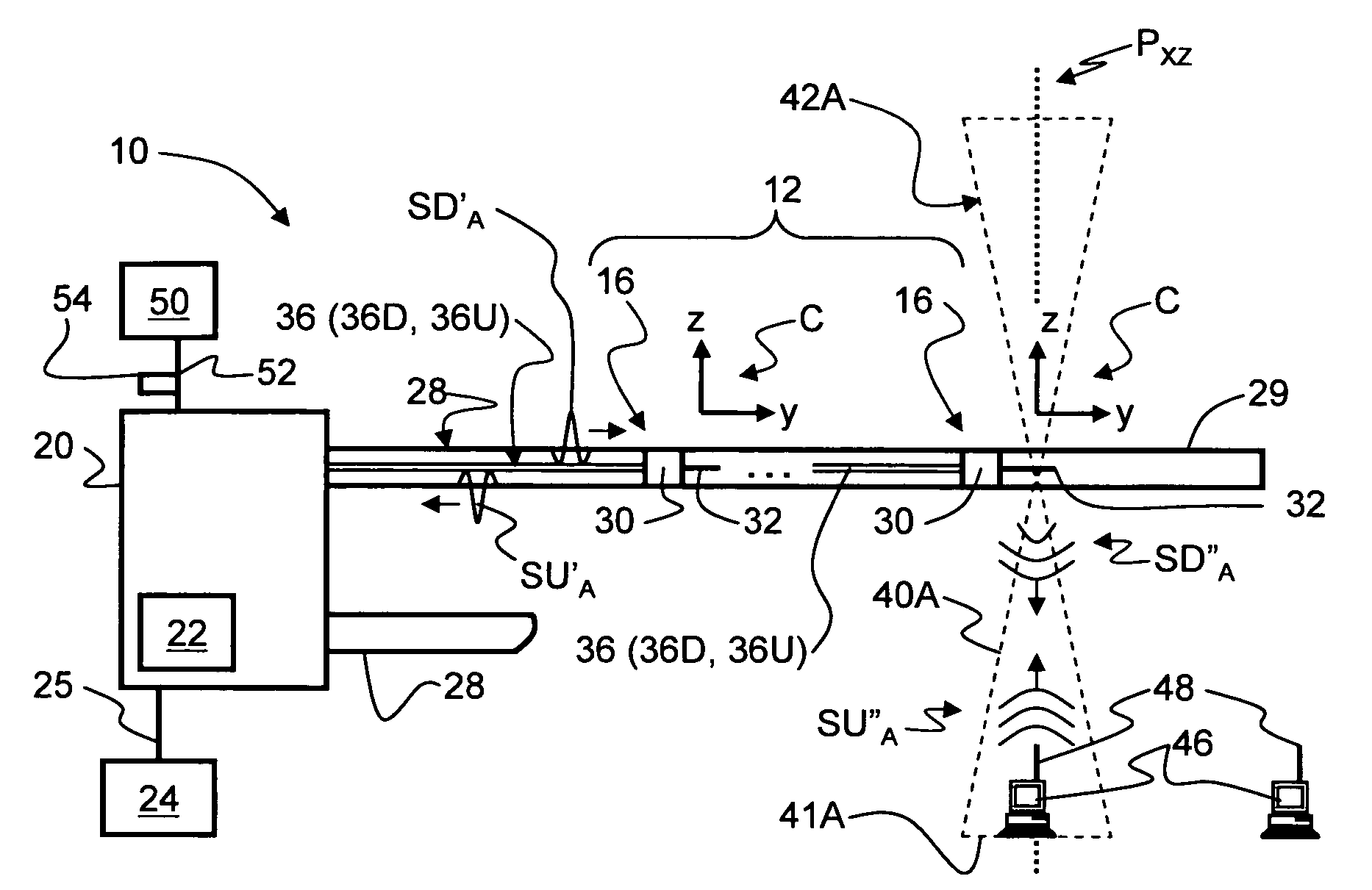
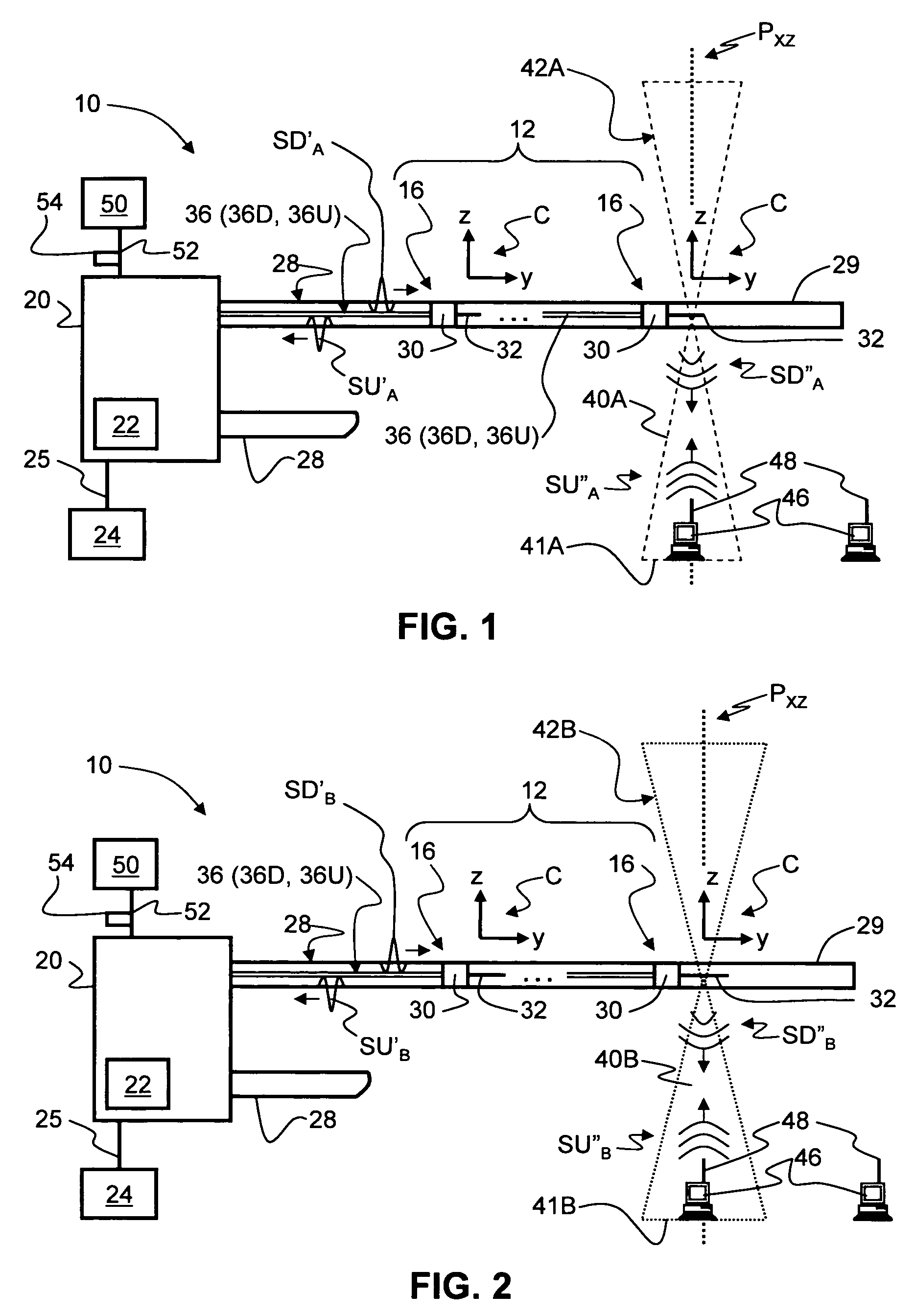
[0032]Also, the term “redundant transponder array” is used herein to describe the array of two or more transponders as adapted according to the present invention to provide backup picocellular coverage for one or more failed transponders in the array. In addition, the term “picocell area” is used to describe the coverage area or “footprint” of a given picocell and is a rough measure of the size of a picocell even though a picocell is three-dime...


PUM


Abstract

A redundant transponder array for a radio-over-fiber (RoF) optical fiber cable is disclosed. The redundant transponder array includes two or more transponders having an antenna system. The antenna system has first and second antennas adapted to form first and second substantially co-located picocells when operated at respective first and second frequencies. The second antenna is adapted to form a picocell that extends into the adjacent picocell when operated at the first frequency. A transponder thus can serve as a backup transponder to a failed adjacent transponder by redirecting the first-frequency signal sent to the failed transponder to the second antenna of the adjacent transponder.

Description

CROSS-REFERENCE TO RELATED APPLICATIONS[0001]This application is a continuation-in-part of U.S. patent application Ser. No. 11 / 454,581, entitled “Transponder for a Radio-over-Fiber Optical Fiber Cable,” filed on Jun. 16, 2006, which application is incorporated by reference herein in its entirety.BACKGROUND OF THE INVENTION[0002]1. Field of the Invention[0003]The present invention relates generally to radio-over-fiber (RoF) systems, and in particular relates to optical fiber cables for such systems that support radio-frequency (RF) transponders.[0004]2. Technical Background[0005]Wireless communication is rapidly growing, with ever-increasing demands for high-speed mobile data communication. As an example, so-called “wireless fidelity” or “WiFi” systems and wireless local area networks (WLANs) are being deployed in many different types of areas (coffee shops, airports, hospitals, libraries, etc.). The typical wireless communication system has a head-end station connected to an access ...

Claims


Application Information

Patent Timeline
Patent Type & Authority Patents(United States)
IPC IPC(8): H04B10/00
CPCH01Q9/285H04W24/04H04B10/25756
Inventor SAUER, MICHAELKOBYAKOV, ANDREY
Owner CORNING OPTICAL COMM LLC
Why Eureka
Try Eureka