Radio-Over-Fiber (RoF) System for Protocol-Independent Wired and/or Wireless Communication

a radio-over-fiber, protocol-independent technology, applied in the field of wired and/or wireless communication systems employing a radio-over-fiber (rof) communication system, can solve the problems of affecting the service life of the system, and requiring complex amplifying and/or repeating requirements. achieve the effect of enhancing coverage, low loss, and high bandwidth

Active Publication Date: 2011-05-19
CORNING OPTICAL COMM LLC
View PDF18 Cites 33 Cited by
  • Summary
  • Abstract
  • Description
  • Claims
  • Application Information

AI Technical Summary

Benefits of technology

[0010]The systems and methods disclosed herein can be configured to overcome the limitations of traditional wired and / or wireless (“wired / wireless”) peer-to-peer communications by combining the low loss, high bandwidth nature of optical fiber with an appropriate optical switching network to enhance coverage (where needed). In one embodiment, the optically-switched fiber optic wired / wireless communication system is a RoF-based link system. In another embodiment, the RoF-based link system is nearly protocol transparent (i.e., independent of protocol).
[0011]The optically-switched fiber optic wired / wireless communication systems and methods disclosed herein may include dense fiber cable deployment (as in picocell), which facilitates cell-to-cell peer-to-peer communication. By taking advantage of the fiber cable architecture of the optically-switched fiber optic wired / wireless communication system, such as a RoF Wireless Local Area Network (WLAN) picocell system, the peer-to-peer communication range is extended to be cell-to-cell. In this regard, devices in any two cells can communicate in the peer-to-peer mode independent of their physical distance, such that the peer-to-peer range extends across entire indoor installation areas.
[0012]In addition, the optically-switched fiber optic wired / wireless communication systems and methods disclosed herein can use optical cable links that are nearly transparent to wireless protocols, thereby eliminating proprietary protocol compliance requirements. Thus, a broad variety of current applications / equipment are supported without any infrastructure upgrade, including switched video connection, switched video with Internet connection, peer-to-peer proprietary protocol equipment (e.g. medical), peer-to-peer videoconferencing, and broadcast capability (cellular and video). In addition, future applications / equipment will be possible without any infrastructure upgrade.
[0013]The optically-switched fiber optic wired / wireless communication system and method disclosed herein take advantage of a local wireless network, such as a WLAN, to initiate peer-to-peer switching, because the switching only needs a very low data rate connection. Multiple input options may be supported, such as a radio frequency (RF) cable / antenna input, an optical fiber input, and an electrical power input. Multiple output options can be used, including an RF cable / antenna output, an optical fiber output with optical / electrical conversion, an optical fiber output with the E / O conversion bypassed, and an electrical power output. The optically-switched fiber optic wired / wireless communication system disclosed herein can be upgraded to higher frequencies, such as 60 Gigahertz (GHz).

Problems solved by technology

Wired and wireless peer-to-peer analog and digital communications are generally limited in range and coverage, respectively.
Enhancing the range of wired peer-to-peer connections may require complicated amplifying and / or repeating requirements.
Extending the coverage of wireless peer-to-peer connections typically requires a denser antenna deployment and / or transmitted power increase, which may be limited by government regulations, wireless standards, and battery peak power and energy storage considerations.

Method used


Image

  • Radio-Over-Fiber (RoF) System for Protocol-Independent Wired and/or Wireless Communication
  • Radio-Over-Fiber (RoF) System for Protocol-Independent Wired and/or Wireless Communication
  • Radio-Over-Fiber (RoF) System for Protocol-Independent Wired and/or Wireless Communication

Examples


Embodiment Construction

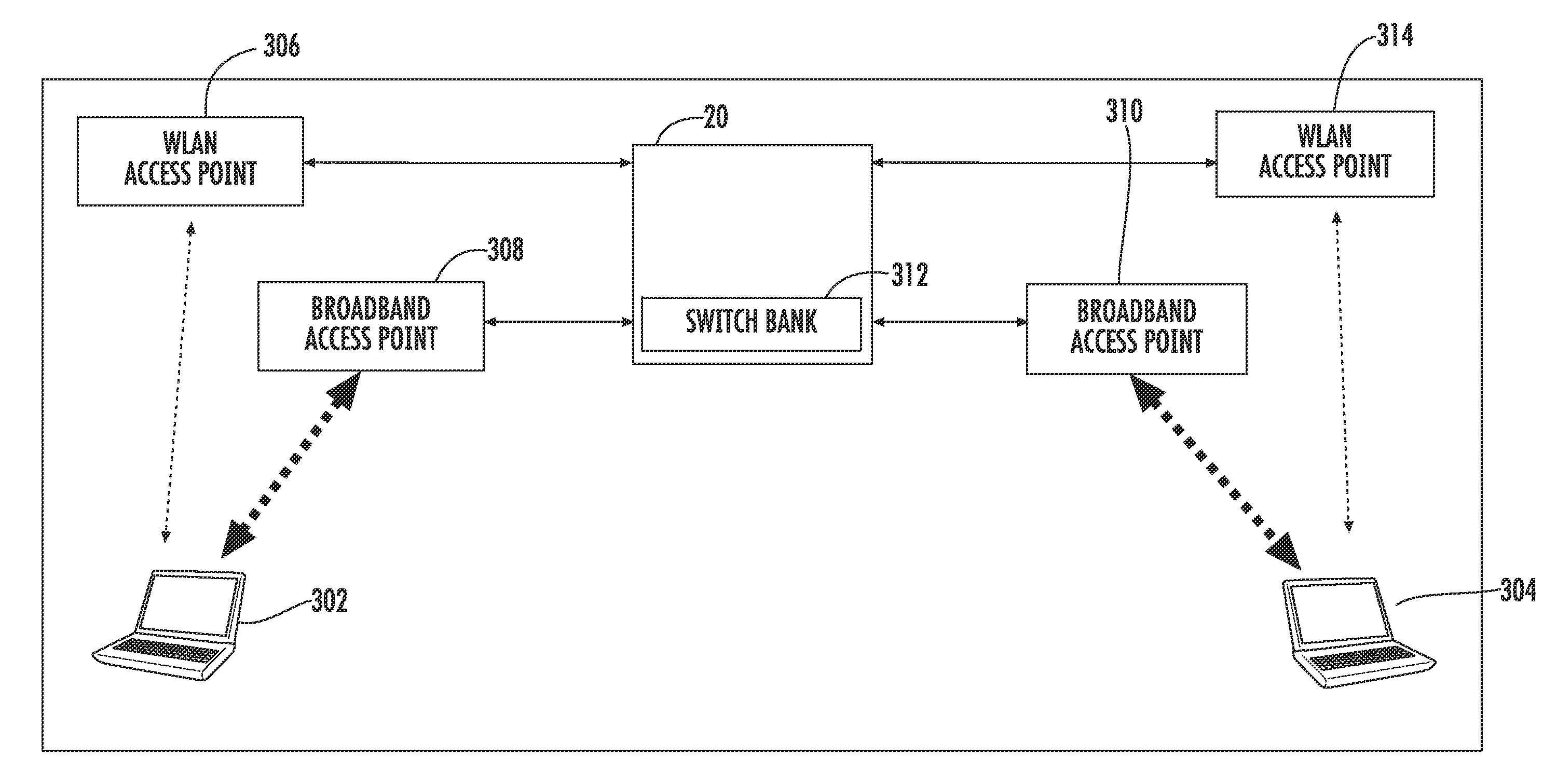
[0008]Embodiments disclosed in the detailed description include optically-switched fiber optic wired and / or wireless communication systems and related methods to increase the range of wired and / or wireless peer-to-peer communication systems. In one embodiment, the optically-switched fiber optic wired and / or wireless communication system may include a head-end unit (HEU) having an optical switch bank. A plurality of fiber optic cables, each of the plurality of fiber optic cables comprising at least one optical fiber, are configured to carry a Radio-over-Fiber (RoF) signal from the HEU to a plurality of remote access points. A first one of the plurality of remote access points is configured to form a corresponding first cellular coverage area where a first peer device is located. A second one of the plurality of remote access points is configured to form a corresponding second, different cellular coverage area where a second peer device is located. The optical switch bank is configure...


PUM


Abstract

An optically-switched fiber optic communication system, such as a Radio-over-Fiber (RoF) based optical fiber link system, may be used to increase the range of peer-to-peer communications. The optically-switched fiber optic communication system may include a head-end unit (HEU) having an optical switch bank. Fiber optic cables comprising optical fibers optically couple the HEU to one or more remote access points in different coverage areas. The optical switch bank in the HEU provides a link between the remote access points in the different coverage areas such that devices in the different cellular coverage areas can communicate with each other over the optical fibers through the HEU. By using the optically-switched fiber optic communication system, the range and coverage of communication between devices may be extended such that devices in different coverage areas and devices using different communication protocols can communicate.

Description

BACKGROUND[0001]1. Field of the Disclosure[0002]The technology of the disclosure relates to wired and / or wireless communication systems employing a Radio-over-Fiber (RoF) communication system.[0003]2. Technical Background[0004]Wireless communication is rapidly growing, with ever-increasing demands for high-speed mobile data communication. As an example, so-called “wireless fidelity” or “WiFi” systems and wireless local area networks (WLANs) are being deployed in many different types of areas (e.g., coffee shops, airports, libraries, etc.). Wireless communication systems communicate with wireless devices called “clients,” which must reside within the wireless range or “cell coverage area” in order to communicate with an access point device.[0005]One approach to deploying a wireless communication system involves the use of “picocells.” Picocells are radio-frequency (RF) coverage areas. Picocells can have a radius in the range from a few meters up to twenty meters as an example. Combin...

Claims


Application Information

Patent Timeline
Patent Type & Authority Applications(United States)
IPC IPC(8): H04J14/00
CPCH04B10/25754H04W76/02H04W84/12H04W88/085H04W92/20H04B10/25751H04N7/15H04W88/08H04W76/10H04Q11/0067H04W16/26
Inventor GEORGE, JACOBSAUER, MICHAELTHELEN, DEAN M.
Owner CORNING OPTICAL COMM LLC
Why Eureka
Try Eureka