Recording control point in trace receivers

a control point and trace receiver technology, applied in the field of processing and memory emulation technology, can solve the problems of fictitious performance de-rating factor between cache and flat memory performance, load and change portions of this cycle are generally viewed as non-productive time, and loss of confidence in the capabilities of the devi

Active Publication Date: 2009-09-15
TEXAS INSTR INC
View PDF6 Cites 2 Cited by
  • Summary
  • Abstract
  • Description
  • Claims
  • Application Information

AI Technical Summary

Problems solved by technology

The load and change portions of this cycle are generally viewed as non-productive time, as one is either waiting for code to download from the host to the target system or looking through files that need changes and making changes with a text editor.
This inaccuracy results in a loss of confidence about the capabilities of the device and leads to fictitious performance de-rating factors between cache and flat memory performance.
While some of the discrepancy between simulated and actual performance is due to inadequate modeling of the cache, there still exists a fundamental problem in modeling system related interactions such as interrupts or DMA accurately.
The period over which the simulator for a given target matures is unfortunately the same time that a developer is attempting to get to market.
The absence of visibility leaves software developers with little else but to speculate about the probable reasons for loss of performance.
In addition on the Texas Instruments TMS320C6000 family Digital Signal Processor (DSP) data memory corruption can also result in program memory corruption causing the CPU execution to crash, as program and data share a unified memory.

Method used


Image

  • Recording control point in trace receivers
  • Recording control point in trace receivers
  • Recording control point in trace receivers

Examples


Embodiment Construction

[0046]Trace data is stored in trace memory as it is recorded. At times, the trace data may be repetitive for extended periods of time. Certain sequences may also be repetitive. This presents an opportunity to represent the trace data in a compressed format. This condition can arise when certain types of trace data are generated e.g., trace timing data is generated when program counter (PC) and data trace is turned off and timing remains on.

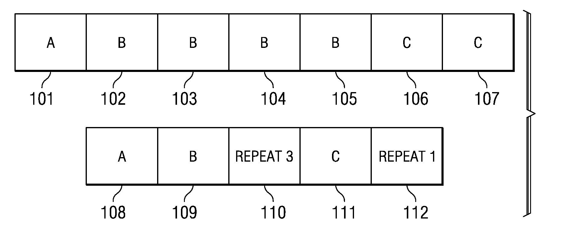
[0047]The trace recording format accommodates compression of consecutive trace words. When at least two consecutive trace words are the same value, the words 2 through n are replaced with a command and count that communicates how many times the word was repeated. The maximum storage for a burst of 2 through n words is two words as shown in FIG. 1, where word 101 does not repeat, words 102,103,104 and 105 are identical and then words 106 and 107 are identical. This sequence compresses as follows—word 108 is the same as word 101, word 109 has the va...


PUM


Abstract

A trace receiver with multiple recording interfaces may be used to record the same input. The historical control point for starting and stopping trace recording is placed very near the front end. A new control point further from the front end allows the front end to continue operation while data is either presented to the memory interface for storage or discarded.

Description

CLAIM TO PRIORITY OF PROVISIONAL APPLICATION[0001]This application claims priority under 35 U.S.C. §119(e) (1) of provisional application Nos. 60 / 680,624, filed May 13, 2005 and 60 / 681,427, filed May 16, 2005.TECHNICAL FIELD OF THE INVENTION[0002]The technical field of this invention is processor and memory emulation technology.BACKGROUND OF THE INVENTION[0003]During applications code development, the development team traverses a repetitive development cycle shown below hundreds if not thousands of times:[0004]1. Building code—compile and link a version of applications code[0005]2. Loading code—loading the code into real hardware system or a software model[0006]3. Debugging / Profiling code—chasing correctness or performance problems[0007]4. Making changes—making source code edits, or changing the linker directives[0008]The load and change portions of this cycle are generally viewed as non-productive time, as one is either waiting for code to download from the host to the target syste...

Claims


Application Information

Patent Timeline
Patent Type & Authority Patents(United States)
IPC IPC(8): G06F11/00
CPCG06F11/3636
Inventor SWOBODA, GARY L.
Owner TEXAS INSTR INC
Why Eureka
Try Eureka