Machining apparatus

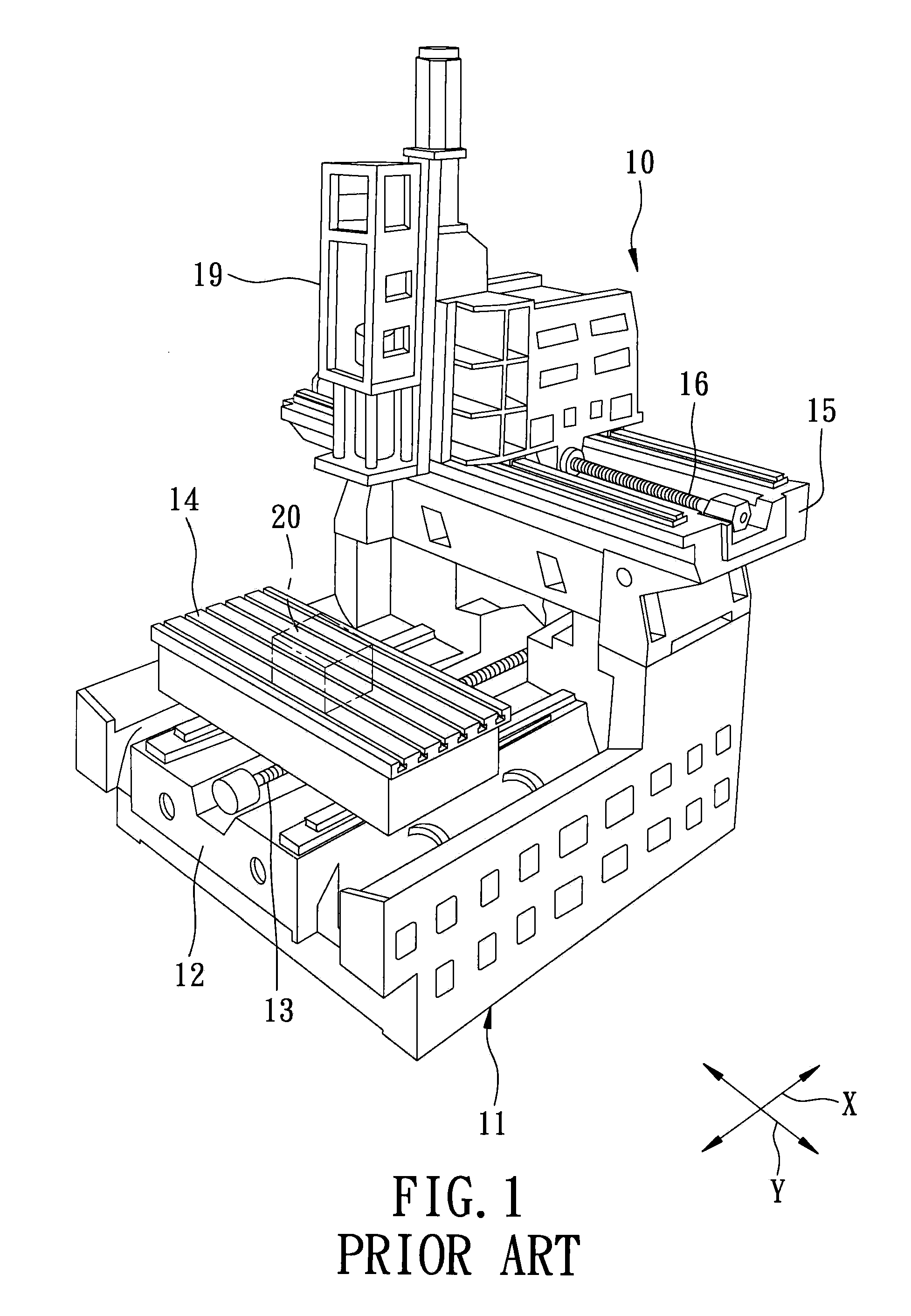
a technology of machining apparatus and machining machine, which is applied in the direction of manufacturing tools, metal-working machine components, planing/slotting apparatus, etc., can solve the problems of inflexibility and inefficiency of the conventional machining apparatus b>10/b>, and achieve the effect of relative flexibility and efficiency

Active Publication Date: 2009-09-22
BUFFALO MACHINERY +1
View PDF15 Cites 22 Cited by
  • Summary
  • Abstract
  • Description
  • Claims
  • Application Information

AI Technical Summary

Benefits of technology

[0007]Therefore, the object of the present invention is to provide a machining apparatus that is relatively flexible and efficient.

Problems solved by technology

The aforementioned conventional machining apparatus 10 is disadvantageous in that, since it includes only one workbench 14, the conventional machining apparatus 10 is relatively inflexible and inefficient.

Method used


Image

  • Machining apparatus
  • Machining apparatus
  • Machining apparatus

Examples


Embodiment Construction

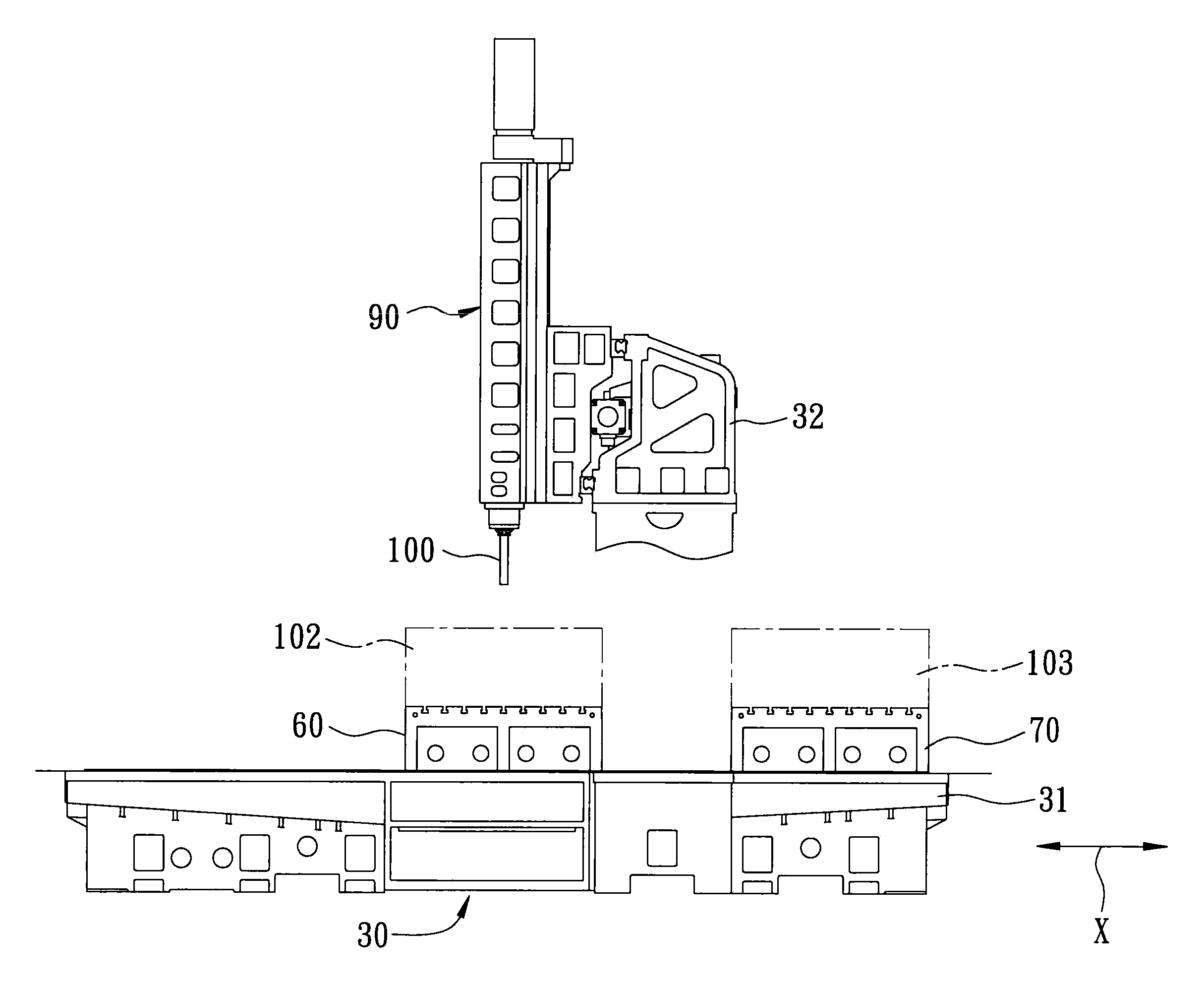
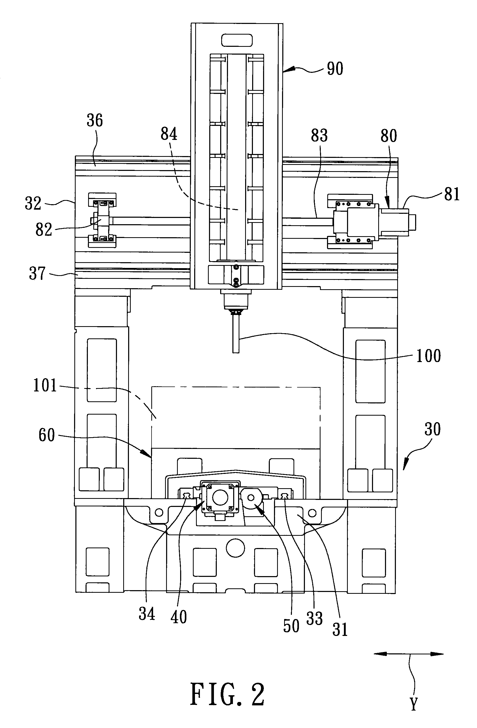
[0016]Referring to FIGS. 2 and 3, the preferred embodiment of a machining apparatus according to this invention is shown to include a support frame 30, first and second workbenches 60, 70, first and second operable units 40, 50, a tool-mounting unit 90, and a third operable unit 80.

[0017]The support frame 30 includes a first horizontal frame part 31, and a second horizontal frame part 32 disposed above the first horizontal frame part 31 thereof.

[0018]The first workbench 60 is mounted slidably on the first horizontal frame part 31 of the support frame 30, and is slidable relative to the support frame 30 in a first horizontal direction (X).

[0019]The second workbench 70 is separated from the first workbench 60, is mounted slidably on the first horizontal frame part 31 of the support frame 30, and is slidable relative to the support frame 30 in the first horizontal direction (X).

[0020]The machining apparatus further includes a pair of spaced apart first and second guide rails 33, 34, ea...


PUM

PropertyMeasurementUnit
flexibleaaaaaaaaaa

Abstract

A machining apparatus includes a support frame, first and second workbenches, and a tool-mounting unit. The support frame includes a first horizontal frame part, and a second horizontal frame part disposed above the first horizontal frame part. The first and second workbenches are mounted slidably on the first horizontal frame part of the support frame, and is slidable relative to the support frame in a first horizontal direction. The tool-mounting unit is mounted slidably on the second horizontal frame part of the support frame, and is slidable relative to the support frame in a second horizontal direction transverse to the first horizontal direction.

Description

BACKGROUND OF THE INVENTION[0001]1. Field of the Invention[0002]This invention relates to a machining apparatus, more particularly to a relatively efficient machining apparatus.[0003]2. Description of the Related Art[0004]FIG. 1 illustrates a conventional machining apparatus 10 that includes a support frame 11, a workbench 14, a tool-mounting unit 19, and first and second operable units 13, 16. The support frame 11 includes a first horizontal frame part 12, and a second horizontal frame part 15 disposed above the first horizontal frame part 12 thereof. The workbench 14 is mounted slidably on the first horizontal frame part 12 of the support frame 11, and is slidable relative to the support frame 11 in a first horizontal direction (X). The first operable unit 13 is mounted on the first horizontal frame part 12 of the support frame 11, is coupled to the workbench 14, and is operable so as to move the workbench 14 in the first horizontal direction (X). The tool-mounting unit 19, which ...

Claims


Application Information

Patent Timeline
Patent Type & Authority Patents(United States)
IPC IPC(8): B23C1/06
CPCB23C1/002B23Q1/66Y10T409/308288Y10T409/305264Y10T409/309576
Inventor CHANG, PAULCHEN, TSAIR-RONGROW, JEEN-SHEENTSAI, YUAN-FU
Owner BUFFALO MACHINERY
Why Eureka
Try Eureka