Method and apparatus for the examination of specimens

a specimen and method technology, applied in the field of specimen methods and apparatuses, can solve the problems of failure of detection methods, inconvenient type of aobs, and inability to detect beam paths, and achieve the effect of efficiently separating excitation light and emission light, and influencing the polarization of ligh

Inactive Publication Date: 2009-09-22
CARL ZEISS MICROSCOPY GMBH
View PDF42 Cites 14 Cited by
  • Summary
  • Abstract
  • Description
  • Claims
  • Application Information

AI Technical Summary

Benefits of technology

[0029]Preferably, in the first selector, one or more acousto-optical filters, in particular acousto-optically tunable filters (AOTF) or acousto-optically tunable modulators (AOM) are provided. The advantage of AOTF compared to the AOM technology lies above in that, more than one wavelength or a spectral range can be selected at the same time from a broad spectrum by separating the first order diffraction. This is therefore an important property, because the dyes allow excitation with a dye-dependent spectral width and hence the available laser power of the broadband laser source can be better exploited. Therefore, in connection with the aforementioned optimal tuning of the excitation, as greater flexibility with respect to the spectral width as possible is of great advantage. AOTF's according to the prior art have a very low spectral width or a high spectral sharpness in the region from 0.5 to 2 nm. Conceivable also are technical embodiments of such AOTF's, which realize greater spectral widths with otherwise identical properties, for example, a width of 25 to 30 nm for a mean wavelength of 490 nm, and a width of 60 to 65 nm for mean wavelength of 670 nm. The width of the spectral window of an AOTF is as a rule an invariable property of the system.
[0036]It is preferable if a flexible main dichroic beam splitter is provided in the separators, in which the illumination light and the emission light are spectrally resolved and are modified and deflected in dependence on the wavelength. With the modification in dependence on the wavelength, it is possible to separate the excitation light and the emission light efficiently and to guide it to the correct port. In this way, the optical path can be influenced by the mechanical elements in dependence on the wavelength, as described, for example, in U.S. Pat. No. 5,751,417, U.S. Pat. No. 6,633,381 B2 and U.S. Pat. No. 6,377,344 B2 (incorporated by reference herein). Another alternative is to influence the polarization of the light by means of a so-called Spatial Light Modulators (SLM), based, for instance, on liquid crystals.

Problems solved by technology

However, the details concerning how the microscope itself is to be embodied, enabling it to use the broadband light in a suitable manner for various methods of examination, are not provided in the patent.
One must note, however, that in this embodiment there is the disadvantage that considerable losses result in the detection beam path.
In particular, in fluorescence microscopy, these losses can lead to the failure of the method.
For a continuously tunable or broadband excitation from ultraviolet to near-infrared spectral range, this type of AOBS is not suitable.
Besides that, such an AOBS, which is designed for excitation with narrowband laser lines, possesses only a small spectral selection width, and hence has low efficiency particularly in the context of a broadband light source.
A flexible adaptation of a continuous spectrum to a method of examination is thus not possible.
This disadvantage, namely, that only one or more discrete lines of the spectrum can be selected for the excitation, applies also to the main dichroic beam splitters, which use a polarizing rotation by means of AOTF for the spectral separation.
The arrangement described there has the disadvantage that three prism spectrometers—one each before and after the dividing element in the excitation beam path, and one in the detection beam path—are necessary.
This considerably increases the complexity and the proneness of the arrangement to fail.
Further, it is also limited to parallel confocal microscopes with band illumination.
Besides that, the variant described in U.S. Pat. No. 6,633,381 B2 has the disadvantage that due to the fixed elements, discrete, predefined wavelength ranges can be separated and detected.
Therefore, the solutions described above do not exploit the full potential of the broadband emitting or variable broadband light sources in the context of their possible applications.
However, many object-specific factors, which can have a considerable influence on the results of the measurement, cannot be taken into consideration therein.
Another example is the appearance of the unknown fluorophores in the object, which can lead—as in the so-called autofluorescence—to undesirable cross excitations.

Method used


Image

  • Method and apparatus for the examination of specimens
  • Method and apparatus for the examination of specimens
  • Method and apparatus for the examination of specimens

Examples


Embodiment Construction

[0060]In describing preferred embodiments of the present invention illustrated in the drawings, specific terminology is employed for the sake of clarity. However, the invention is not intended to be limited to the specific terminology so selected, and it is to be understood that each specific element includes all technical equivalents that operate in a similar manner to accomplish a similar purpose.

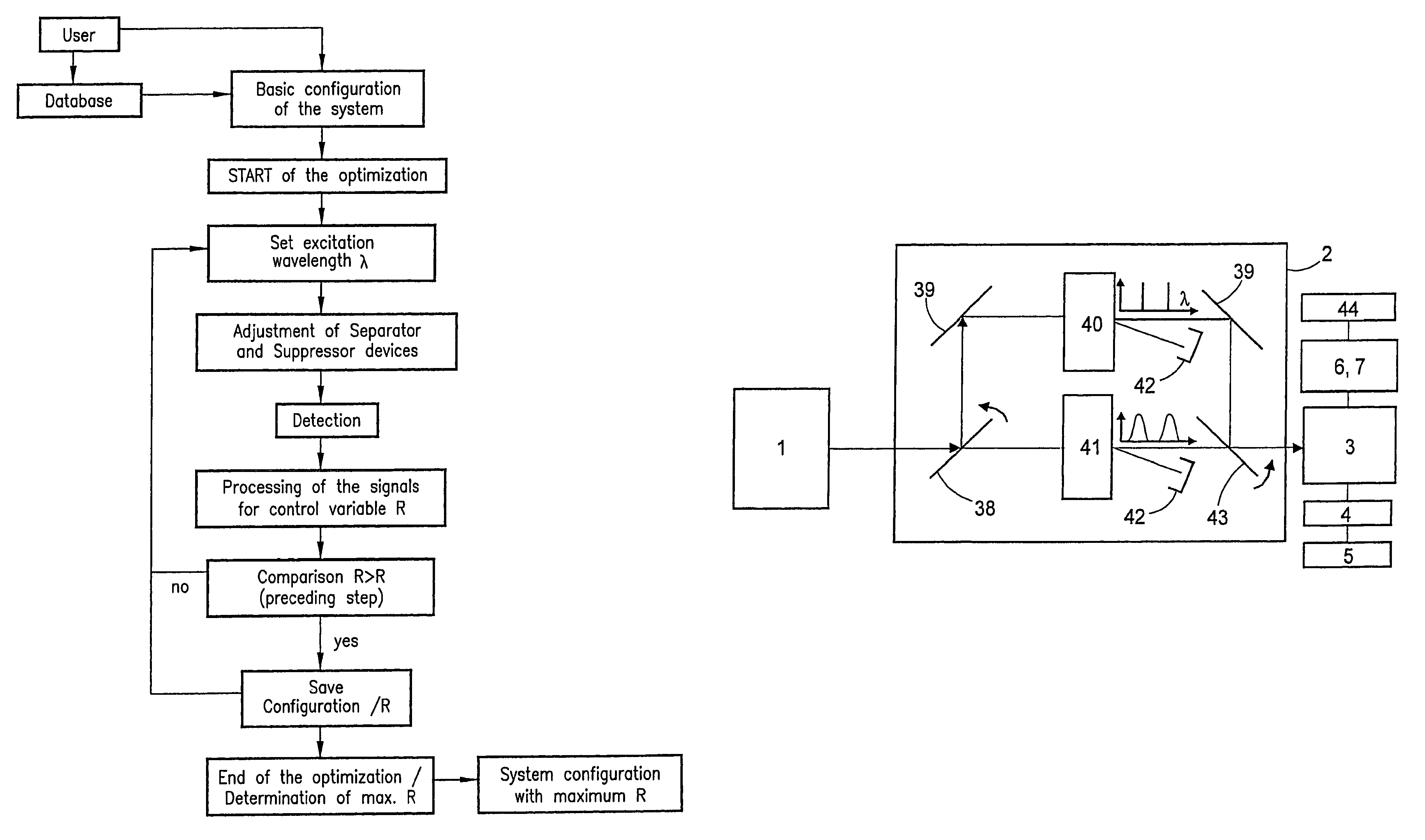
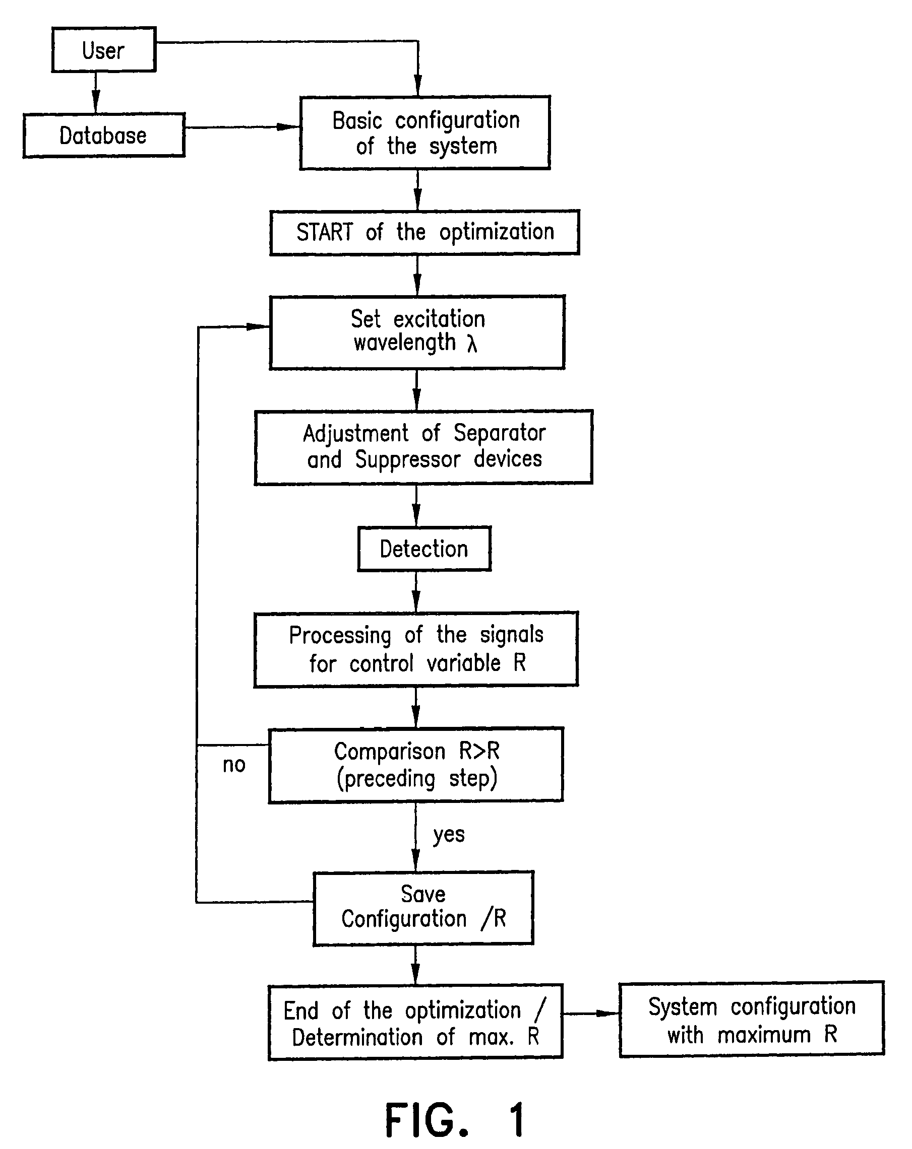
[0061]FIG. 1 shows the procedural sequence of the method for the optimization of the excitation wavelengths for a fixed detection wavelength range. The user can do the basic configuration of the system for the start of the optimization himself or use the emission and detection spectra stored in the database by entering the dyes present in the specimen. In the latter case, the basic configuration of the system takes place automatically on the basis of the information in the database. The other optimization variables, such as the step lengths, excitation and detection bands are set up autom...


PUM


Abstract

A method in which specimens are examined using a microscope. For an illuminated specimen, spatially coherent light with at least one continuous wavelength range or a continuously tunable wavelength range is generated, and one or more wavelengths or wavelength ranges in the illumination light are selected in dependence on the prespecified method of examination. The specimen is then illuminated with the illumination light with the selected wavelengths or wavelength ranges, the illumination light and the emission light coming from the specimen are then subsequently separated, whereby the back radiated illumination light is suppressed in the detection beam before the detection and the emission light is detected. In such a method, the selection of the wavelengths or the wavelength ranges of the illumination light is tuned by means of the separation of the detection light and the illumination light and the suppression of the illumination light in such a manner that a prespecified control variable (R) is optimized.

Description

BACKGROUND OF THE INVENTION[0001]1. Field of the Invention[0002]The invention relates to a method, in which specimens are examined with a microscope. For the illumination of the specimen, spatially coherent light in at least one continuous or continuously tunable wavelength range is generated. One or more wavelengths or ranges of wavelengths of the illumination light are selected in dependence on the specimen and / or the specified method of examination. The specimen is illuminated with the selected wavelengths or wavelength ranges. The illumination light and the emission light coming from the specimen are separated into separate beam paths. The illumination light is radiated back by the specimen and is suppressed in the beam path before the detection, and the emission light is detected. Further, the invention relates also to microscopes with which a specimen is analyzed—in particular by means of such a method. The present invention is concerned with the problem of the use of light so...

Claims


Application Information

Patent Timeline
Patent Type & Authority Patents(United States)
IPC IPC(8): G02B21/06
CPCG01N21/6458G02B21/0032G02B21/008G02B21/16G02B21/0076Y10S359/90
Inventor WILHELM, STEFANSIMBURGER, EVAKEMPE, MICHAEL
Owner CARL ZEISS MICROSCOPY GMBH
Why Eureka
Try Eureka