Door closure system

a door and opening technology, applied in the field of door opening technology, can solve problems such as poor operation of the door structur

Active Publication Date: 2009-10-06
RALPH ELLERKER 1795
View PDF8 Cites 1 Cited by
  • Summary
  • Abstract
  • Description
  • Claims
  • Application Information

AI Technical Summary

Benefits of technology

[0020]This movement can be achieved quickly and efficiently in accordance with the applicant's co-pending patent application and thereby ensures that the environments on each side of the door are exposed to each other through the opening for a minimum period of time.
[0022]It is found by controlling the flow of air through the cavity in the door as herein described, so the air is found to act more substantially uniformly across the area of the walls of the door and thereby further minimising or indeed eliminating the creation of frost on the walls or in the vicinity thereof.

Problems solved by technology

A problem which is often experienced with openings between environments which are required to be held at different temperatures, is the need to provide a closure in the form of a door for the opening, which door is operable to move between opened and closed positions and in particular, once opened, to return to a closed condition as quickly as possible so as to be able to maintain the temperature in the cooler environment and thereby allow the maintenance of the goods in the cooler environment at the required temperature.
A further problem which is experienced is the creation of condensation on the door itself which can lead to, firstly, the gathering of water or liquid in the vicinity of the door and, if frost forms, the malfunction or poor operation of the door structure.

Method used


Image

  • Door closure system
  • Door closure system
  • Door closure system

Examples


Embodiment Construction

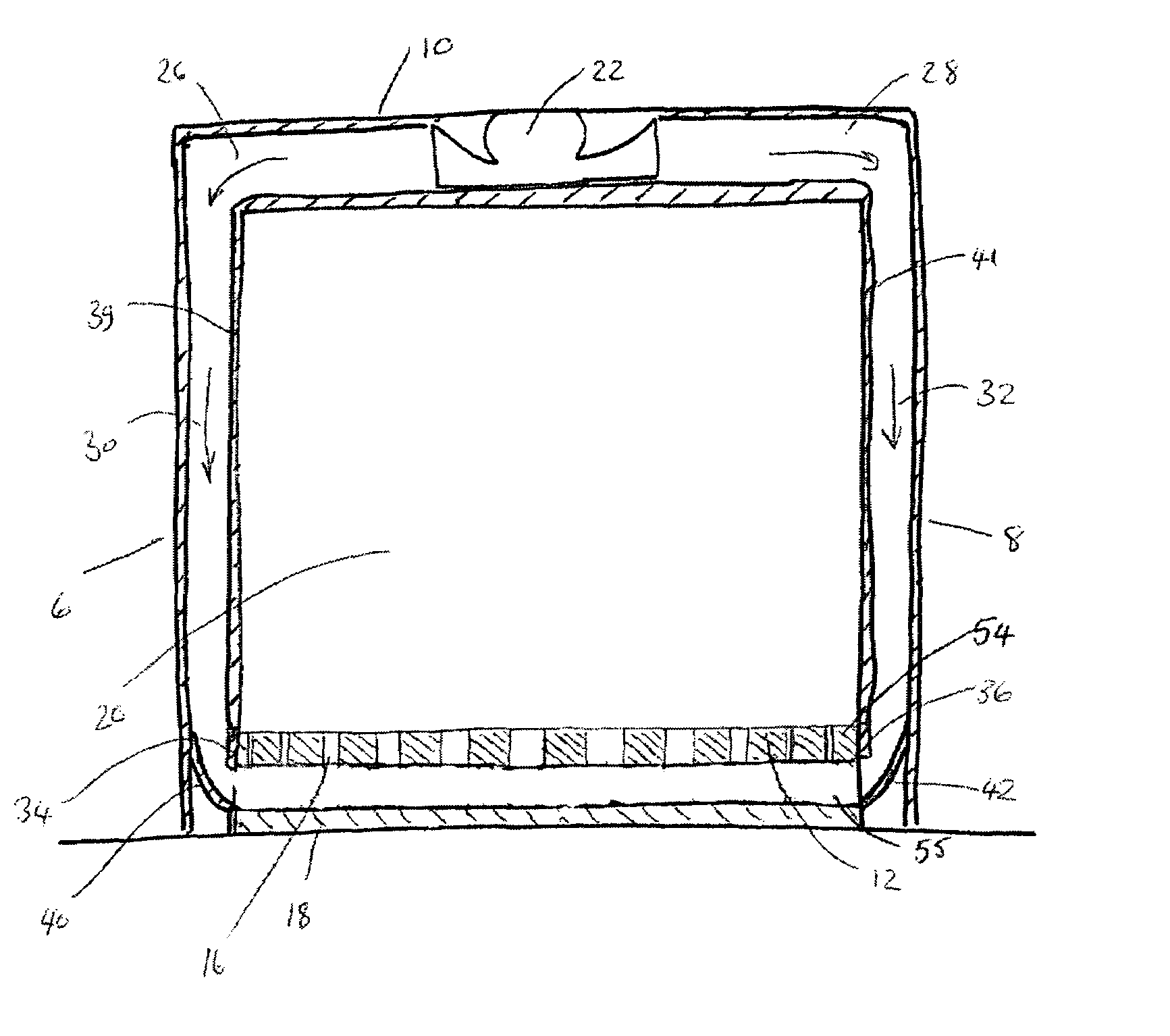
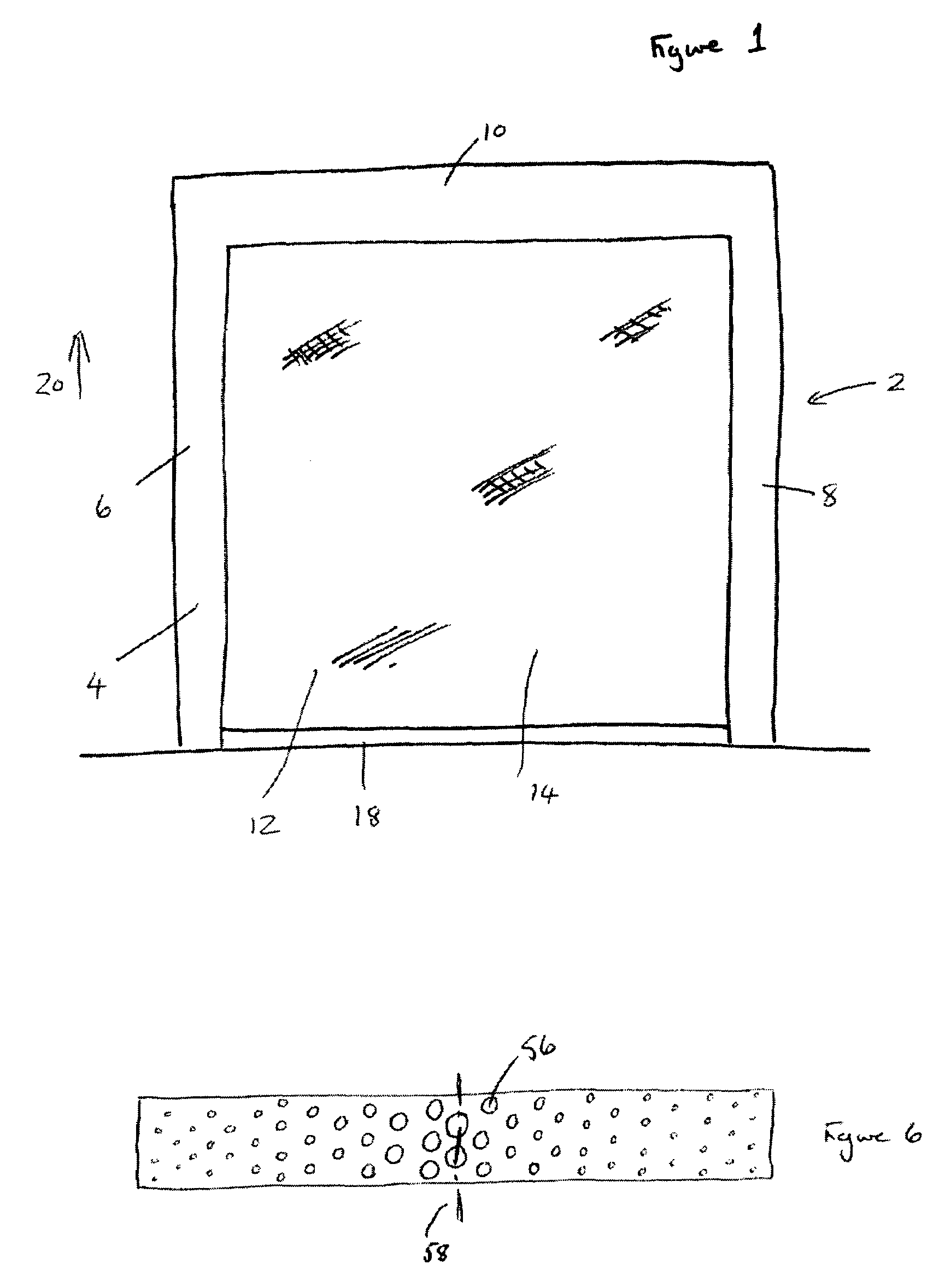
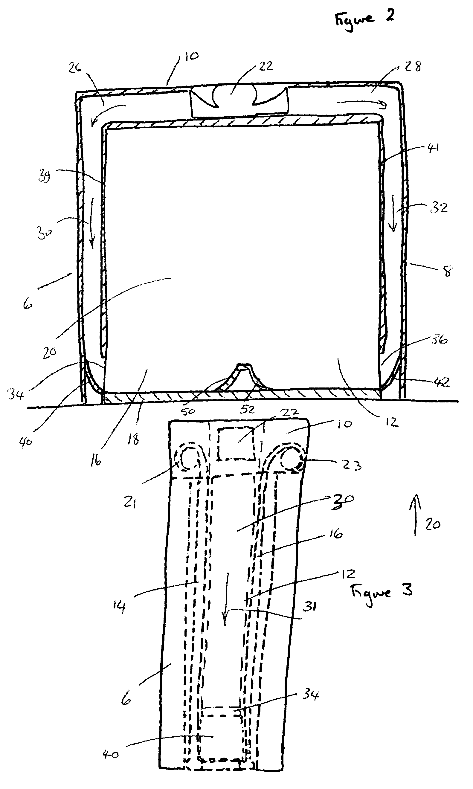
[0032]Referring now to the drawings, there is illustrated a door structure in accordance with one embodiment of the invention. The door structure 2 comprises a door frame 4 formed of side members 6, 8 and top member 10 which in conjunction with the floor on which the frame is mounted define an opening in which the door 12 is provided. The door 12 is formed by a first wall 14 and a spaced, second wall 16 which together, in conjunction with a bottom beam or layer 18 form a cavity 30. The door structure is shown in a closed condition but can be moved to an open condition by a mechanical drive means of rollers 21, 23 to move the door in direction 20 whereupon the walls of the door, which are flexible to a degree, can be wound and stored at or above the top door frame member 10 in a rolled up form on respective rollers 21, 23. In the open position, persons and / or objects can be moved between the environments on either side of the door and it is found that doors of this type are of partic...


PUM


Abstract

A door structure, said structure for use particularly, although not necessarily exclusively, to selectively close an opening between a first environment which is at a temperature which is lower than the temperature of the environment on the opposing side of the opening. The door is provided with a structure so as to define a cavity therein into which air is caused to flow. The door has formations and a structure so as to encourage uniform air flow through the cavity and hence prevent or minimise the creation of condensation and / or frost on the door structure.

Description

CROSS-REFERENCE TO RELATED APPLICATION[0001]This application claims priority to United Kingdom Application No. 0509919.7 filed on May 16, 2005 by inventors Christine Isobel Schofield and Peter James Howard Rodgers.FIELD OF INVENTION[0002]The invention to which this application relates is to improvements to a door closure system of the type which is particularly, although not necessarily exclusively, of use to be movable between an open and closed position with respect to an environment, on one side, which is held in chilled or freezing temperatures for the storage of goods therein and, on the other side an environment which is substantially at ambient temperature.BACKGROUND OF INVENTION[0003]A problem which is often experienced with openings between environments which are required to be held at different temperatures, is the need to provide a closure in the form of a door for the opening, which door is operable to move between opened and closed positions and in particular, once open...

Claims


Application Information

Patent Timeline
Patent Type & Authority Patents(United States)
IPC IPC(8): E06B7/16E06B7/02E06B9/13E06B9/17
CPCE06B9/582E06B9/08E06B2009/17069
Inventor SCHOFIELD, CHRISTINE ISOBELRODGERS, PETER JAMES HOWARD
Owner RALPH ELLERKER 1795
Why Eureka
Try Eureka