
Method and control unit for ascertaining a capacitance value of a data bus
a data bus and capacitance value technology, applied in the direction of capacitance measurement, resistance/reactance/impedence, instruments, etc., can solve the problem of large variance of electrical capacitance of the overall system
- Summary
- Abstract
- Description
- Claims
- Application Information
AI Technical Summary
Benefits of technology
Problems solved by technology
Method used
Image

Examples
Embodiment Construction
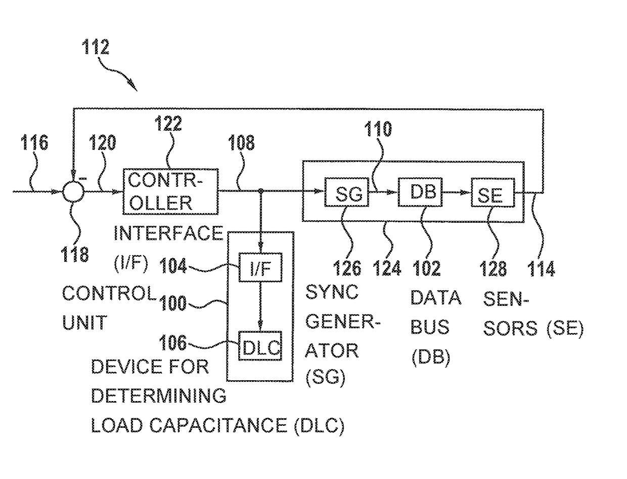
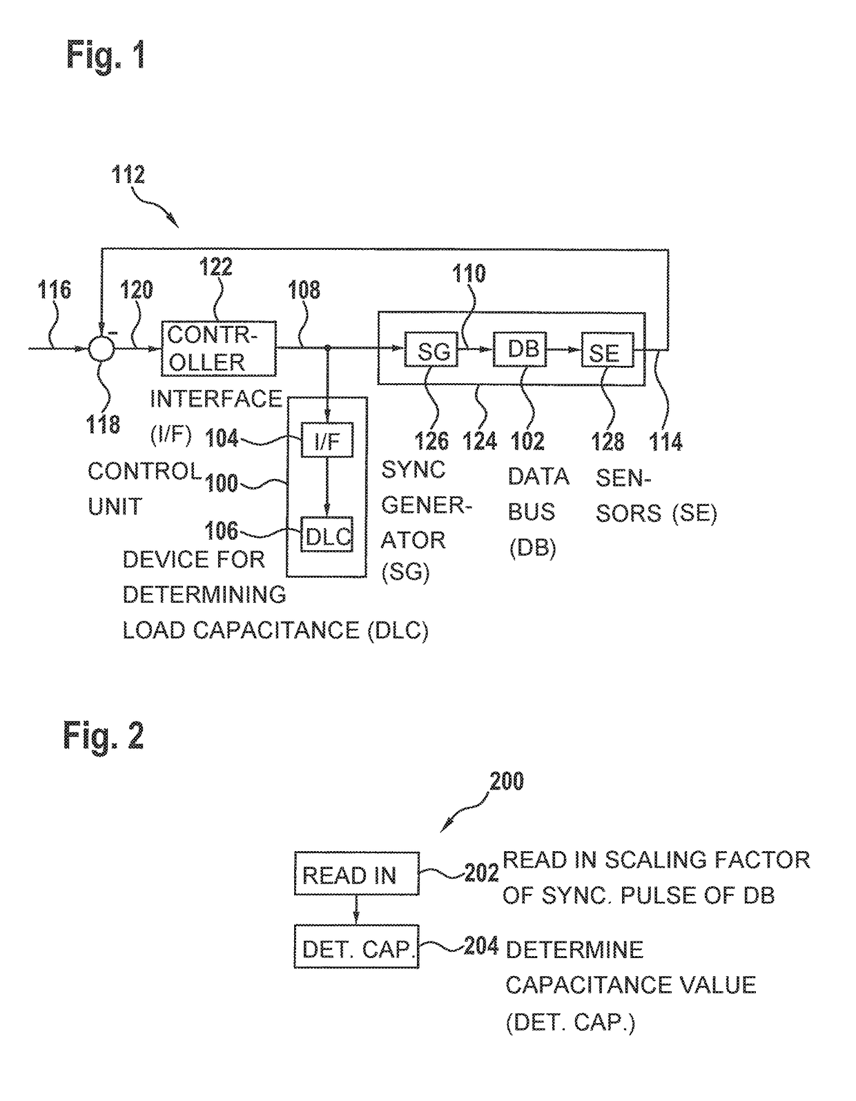
[0033]Peripheral sensors 128 for occupant protection systems generally use current interfaces, for example PAS4 or PSI5, for transmitting sensor data to the central control unit (ECU) 300.
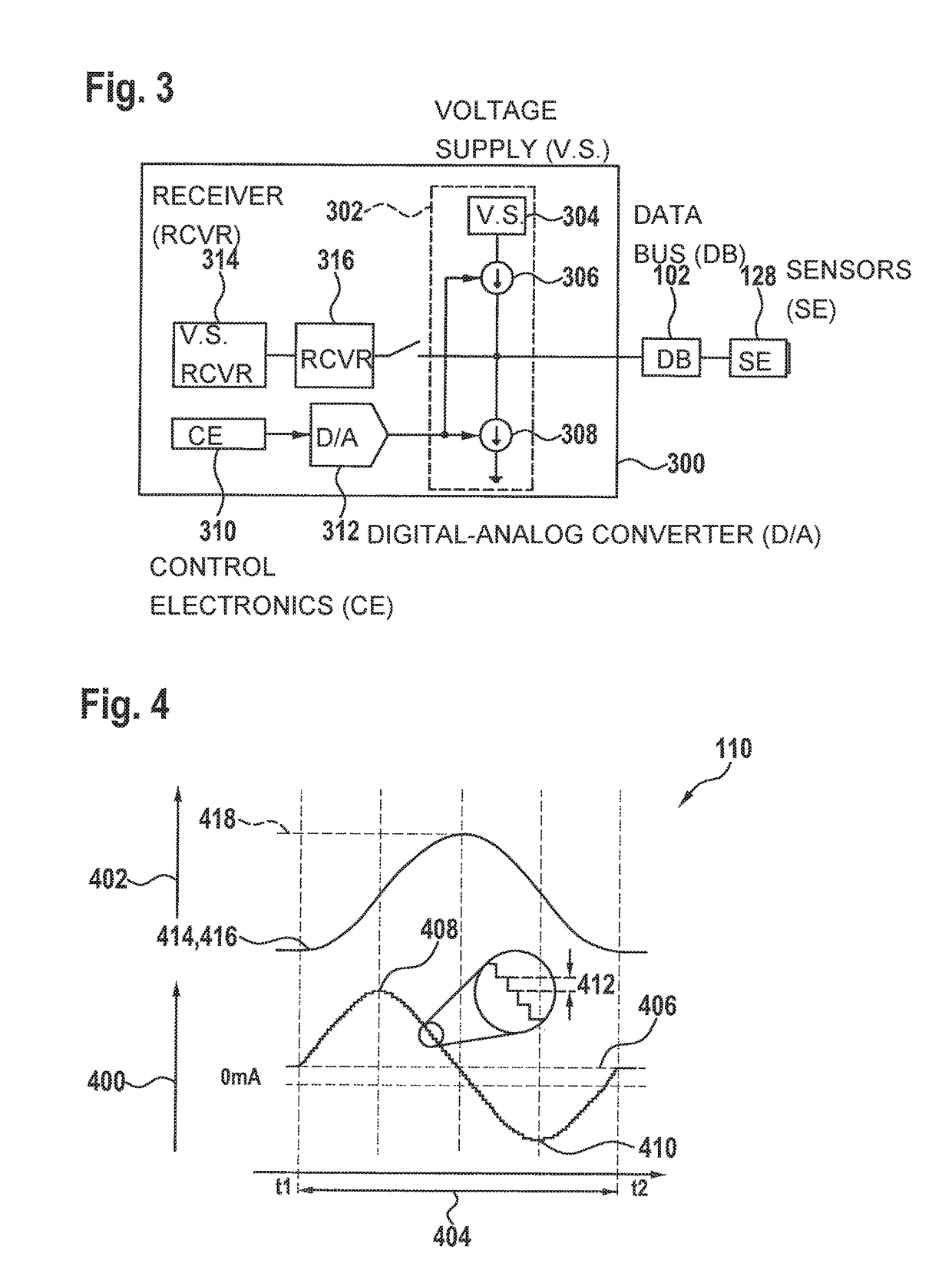
[0034]In current interfaces of the latest generation (PSI5), the bus operation with multiple sensors 128 at a receiver 300 is made possible with the aid of synchronization. For the function of the synchronization, control unit ECU 300 generates a working clock in the form of a voltage pulse which is detected by sensors 128 at bus 102 and identifies the start of a new cycle for the data transmission. This voltage pulse is referred to as a synchronization pulse and is created with the aid of current sources 306 and current sinks 308, which charge or discharge the bus load.
[0035]The different type and number of sensors 128 and filters, depending on the application, in control unit 316 of receiver 300 contribute to the large range of load capacitances which must be tolerated.
[0036]To implement the filt...
PUM
 Abstract
Description
Claims
Application Information