Method and processing device for processing measured data of an image sensor

a processing device and image sensor technology, applied in the field of method and processing device for processing measured data of image sensor, can solve the problem of insufficiently precise image imaging of images by image sensor, and achieve the effect of quick and efficient processing

Pending Publication Date: 2022-02-10
ROBERT BOSCH GMBH
View PDF2 Cites 0 Cited by
  • Summary
  • Abstract
  • Description
  • Claims
  • Application Information

AI Technical Summary

Benefits of technology

[0010]One specific embodiment of the present invention is advantageous in which in the step of reading in, measured data of light sensors are read in, which are respectively situated in a different row and / or a different column on the image sensor in relation to the reference position, in particular the light sensors completely surrounding the reference position. In the present case, a row may be understood to mean an area having a predetermined distance from an edge of the image sensor. In the present case, a column may be understood to mean an area having a predetermined distance from another edge of the image sensor, the edge that defines the column being different from an edge that defines the row. In particular, the edge, by which the rows are defined, may extend in a different direction or perpendicularly with respect to the edge, by which the columns are defined. As a result, areas on the image sensor may be distinguished without the light sensors themselves being positioned symmetrically in rows and columns on the image sensor (image sensor built up in the form of a matrix). Rather, the aim is merely to ensure that the light sensors in the surroundings of the reference position are situated around the reference position at multiple different sides. Such a specific embodiment of the approach presented here offers the advantage that the image data for the reference position may be corrected, taking into account effects or measured values of light sensors that are to be observed in the immediate vicinity around the reference position. For example, a continuously increasing change in the point imaging of a real object from a central area of the image sensor toward an edge area may thus be taken into account or compensated for very precisely.
[0027]Moreover, the present invention provides a processing device that is designed to carry out, control, or implement the steps of one variant of a method provided here in appropriate units. By use of this embodiment variant of the present invention in the form of a processing device, the object underlying the present invention may also be achieved quickly and efficiently.

Problems solved by technology

In conventional optical recording systems, a problem often arises with regard to sufficiently precise imaging of images by an image sensor, due to the fact that, for example, imaging errors of optical components of a real object assume a different type of shape in the center of the image sensor compared to imaging of the object in the edge area of the image sensor.
In particular, due to the color filter mask, all colors of the color filter mask are not available at every location on the image sensor.

Method used


Image

  • Method and processing device for processing measured data of an image sensor
  • Method and processing device for processing measured data of an image sensor
  • Method and processing device for processing measured data of an image sensor

Examples


Embodiment Construction

[0047]In the following description of advantageous exemplary embodiments of the present invention, identical or similar reference numerals are used for the elements having a similar action which are illustrated in the various figures, and a repeated description of these elements is dispensed with.

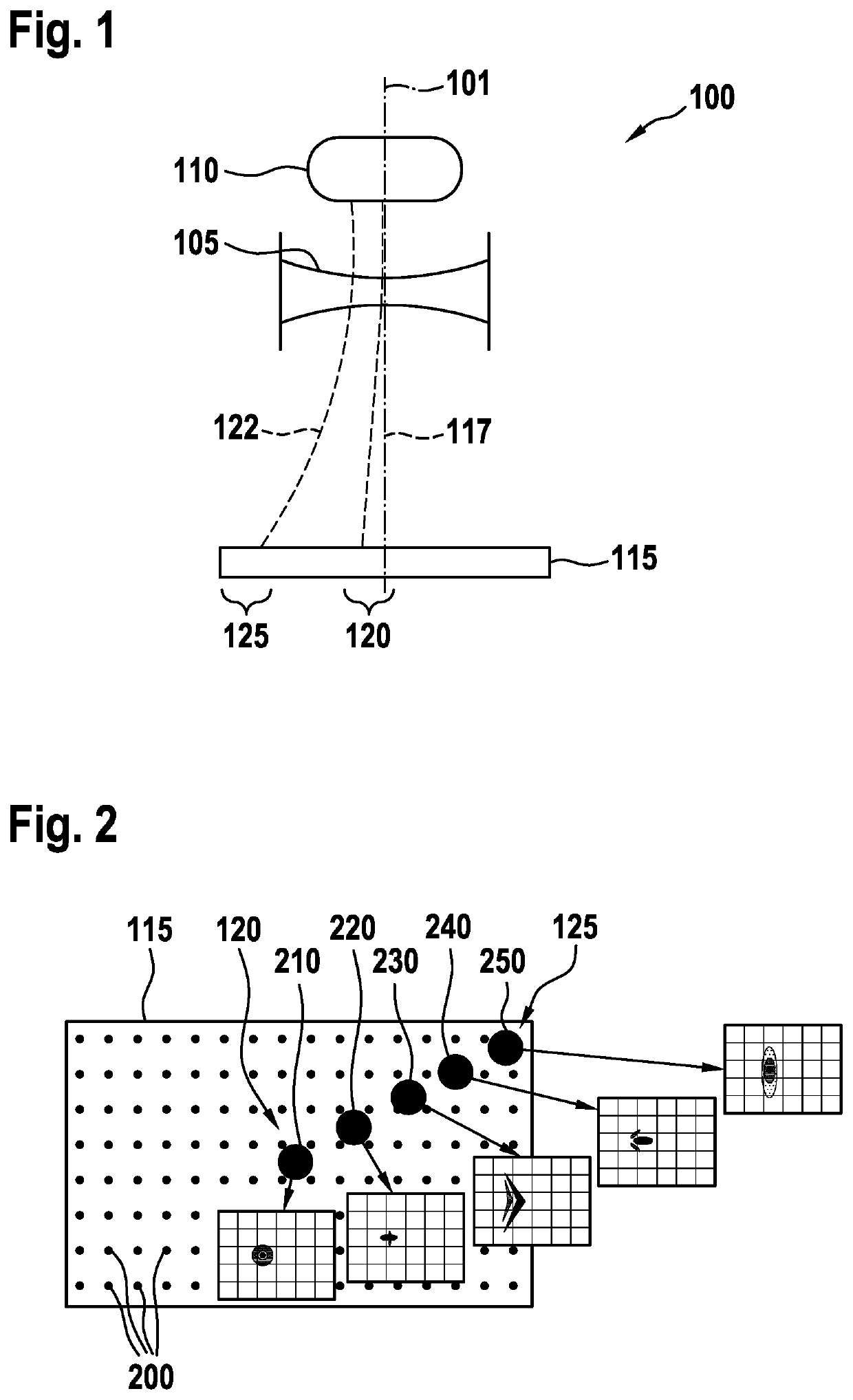
[0048]FIG. 1 shows a cross-sectional view of a schematic illustration of an optical system 100, including a lens 105, oriented in an optical axis 101, through which an object 110, illustrated as an example, is imaged onto an image sensor 115. It is apparent from the exaggerated depiction in FIG. 1 that a light beam 117 striking in a central area 120 of image sensor 115 takes a smaller path through lens 105 than a light beam 122 that passes through an edge area of lens 105 and also strikes in an edge area 125 of image sensor 115. In addition to an effect with regard to a brightness reduction in light beam 122 due to the longer path in the material of lens 105, it is also possible, for exampl...


PUM


Abstract

A method for processing measured data of an image sensor. The method includes reading in measured data that have been recorded by light sensors in the surroundings of a reference position on the image sensor. The light sensors are situated around the reference position on the image sensor. Weighting values are read in, each of which is associated with the measured data of the light sensors in the surroundings of a reference position, the weighting values for light sensors situated at an edge area of the image sensor differing from weighting values for light sensors situated in a central area of the image sensor, and / or the weighting values being a function of a position of the light sensors on the image sensor. The method includes linking the measured data of the light sensors to the associated weighting values to obtain image data for the reference position.

Description

FIELD[0001]The present invention is directed to a method or a processing device. Moreover, the subject matter of the present invention relates to a computer program.BACKGROUND INFORMATION[0002]In conventional optical recording systems, a problem often arises with regard to sufficiently precise imaging of images by an image sensor, due to the fact that, for example, imaging errors of optical components of a real object assume a different type of shape in the center of the image sensor compared to imaging of the object in the edge area of the image sensor. At the same time, different imaging properties of colors or color patterns may occur at different positions of the image sensor, which result in a suboptimal representation or depiction of the real object by the image sensor. In particular, due to the color filter mask, all colors of the color filter mask are not available at every location on the image sensor.SUMMARY[0003]In accordance with example embodiments of the present invent...

Claims


Application Information

Patent Timeline
Patent Type & Authority Applications(United States)
IPC IPC(8): H04N5/235G06T7/70G06K9/62
CPCH04N5/2351G06T2207/20081G06K9/6256G06T7/70H04N23/71H04N25/61H04N25/611H04N23/10G06F18/214
Inventor GEESE, MARCSEGER, ULRICH
Owner ROBERT BOSCH GMBH
Why Eureka
Try Eureka