

Maximum likelihood decoding device, signal evaluating method, and reproducing apparatus
a decoding device and probability technology, applied in the field of probability probability decoding device, signal evaluation method, reproducing apparatus, can solve the problems of above-described bit detection using an analog binary signal, inability to secure a sufficiently low bit error rate, and inability to be appropriate as an indicator of signal quality
- Summary
- Abstract
- Description
- Claims
- Application Information
AI Technical Summary
Benefits of technology
Problems solved by technology
Method used
Image

Examples
first embodiment
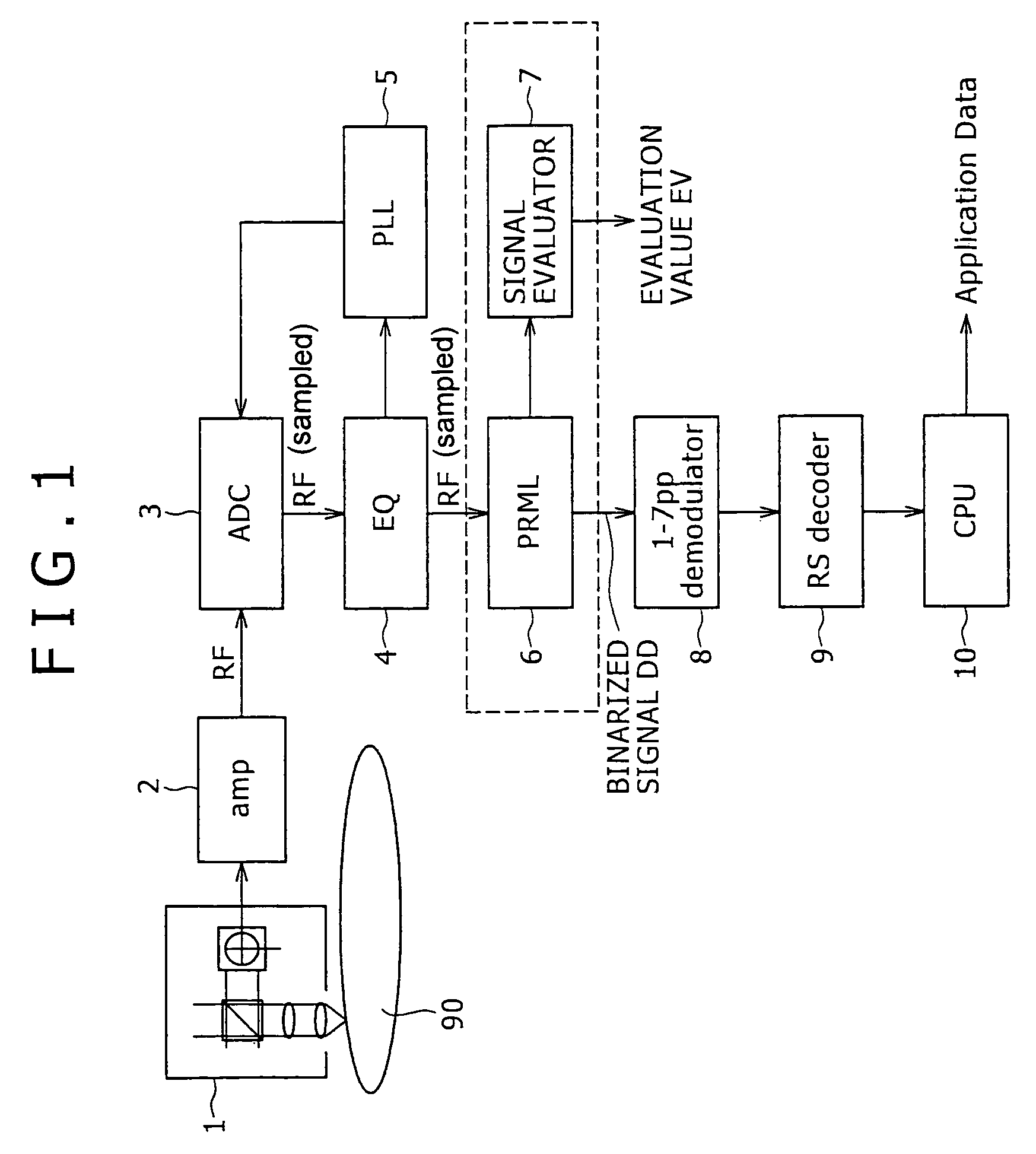
[0059]FIG. 1 is a block diagram showing an outline of a reproduction device according to the present invention.
[0060]As shown in FIG. 1, the reproduction device according to the present embodiment includes a recording medium 90 in the form of a disk such as an optical disk or the like, an optical pickup 1 for reproducing bit information from the recording medium 90, and a preamplifier 2 for converting the signal read by the optical pickup 1 into a reproduced signal (RF signal).
[0061]The reproduction device further includes an A / D converter 3 for subjecting the reproduced signal RF to A / D conversion, an equalizer 4 for adjusting the waveform of the reproduced signal RF for PLL (Phase Locked Loop) processing, and a PLL circuit 5 for reproducing a clock from the reproduced signal RF.
[0062]The reproduction device further includes a PRML (Partial Response Maximum Likelihood) decoder 6 (Viterbi detector) for detecting bit information from the reproduced signal RF and thereby obtaining a b...
second embodiment
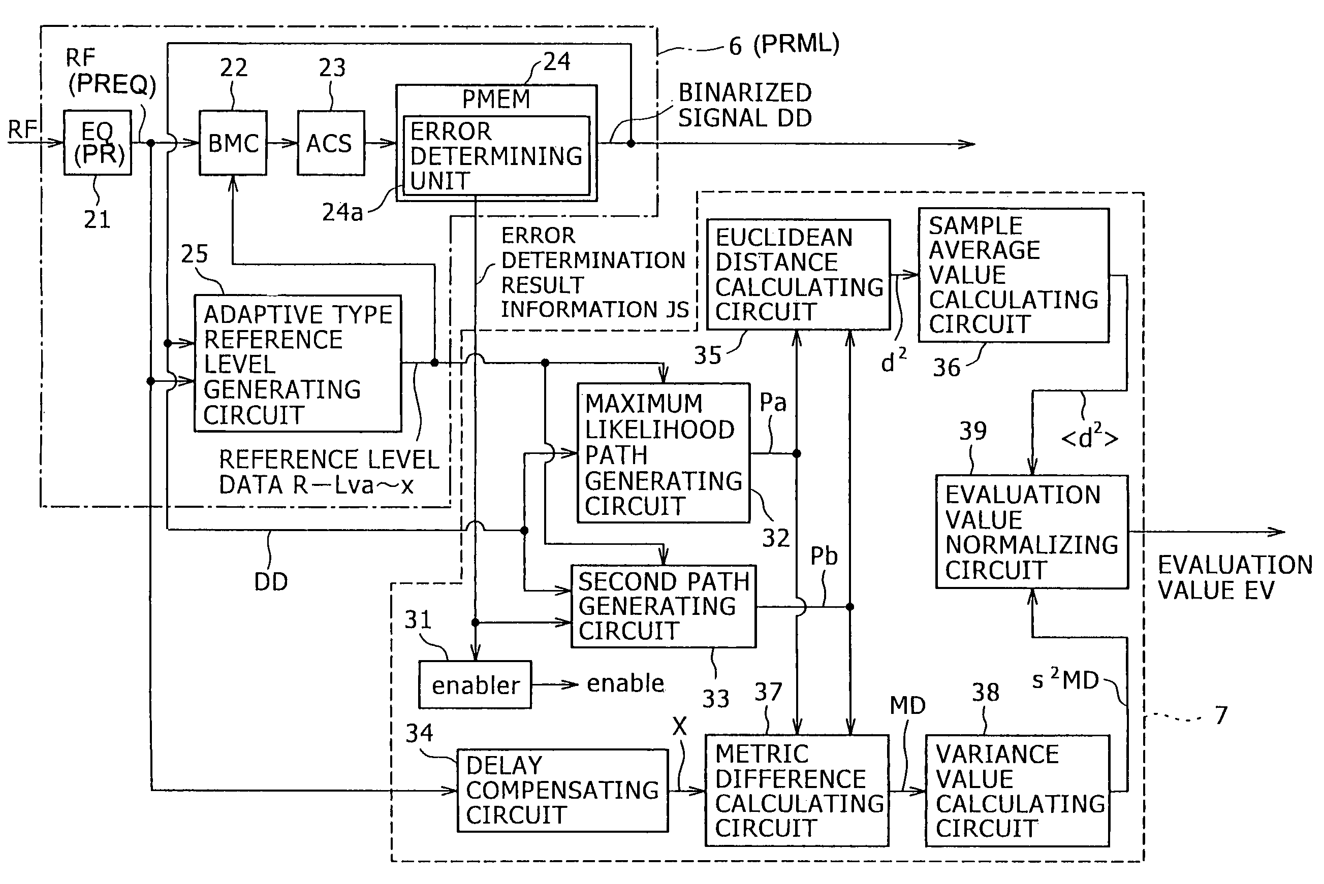
[0231]FIG. 3 shows an example of configuration of a
[0232]Incidentally, in FIG. 3, the parts already described with reference to FIG. 2 are identified by the same reference numerals, and description thereof will be omitted.
[0233]The second embodiment corresponds to a case where the evaluation value EV calculated within the signal evaluator 7 in the foregoing first embodiment is calculated outside the signal evaluator 7.
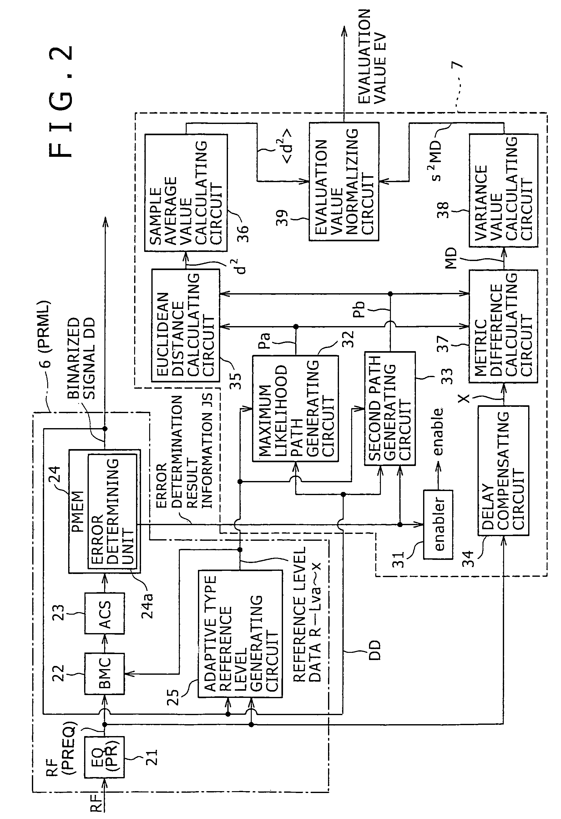
[0234]Specifically, a signal evaluator 7 in this case has a configuration in which the evaluation value normalizing circuit 39 is omitted, and an average value 2> and a variance value σ2MD, generated by a sample average value calculating circuit 36 and a variance value calculating circuit 38, respectively, are output as they are to the outside, as shown in FIG. 3.
[0235]An evaluation value EV in this case can be calculated by providing the evaluation value normalizing circuit 39 shown in FIG. 2 outside the signal evaluator 7, for example. Even when the evaluation value ...
third embodiment
[0239]FIG. 4 shows an example of configuration of a
[0240]Incidentally, in FIG. 4, the parts already described with reference to FIG. 2 are identified by the same reference numerals, and description thereof will be omitted. When the configuration of a PRML decoder 6 and a signal evaluator 7 shown in FIG. 4 is employed, the general configuration of the reproducing apparatus is the same as shown in FIG. 1.
[0241]The third embodiment identifies a type of error between a maximum likelihood path Pa and a second path Pb on the basis of a pattern table, whereas the first and second embodiments refer to the error determination result information JS to identify the error type.
[0242]In FIG. 4, the error determining unit 24a provided within the path memory updating unit 24 is omitted in the PRML decoder 6 in this case.
[0243]The signal evaluator 7 is provided with a pattern detecting circuit and pattern table, 40 as shown in FIG. 4. The pattern detecting circuit and the pattern table that the pat...
PUM
 Abstract
Description
Claims
Application Information