
Wide-bandwidth operational amplifier

a technology of operation amplifier and wide-bandwidth, which is applied in the field of analog electrical circuits, can solve problems such as unstable closed-loop system, physical opamps are not ideal, and amplifier modifications to reduce non-linear distortion

Inactive Publication Date: 2003-06-03
ANALOG DEVICES BV
View PDF10 Cites 22 Cited by
  • Summary
  • Abstract
  • Description
  • Claims
  • Application Information

AI Technical Summary

Benefits of technology

to provide an operational amplifier circuit which can be used to drive difficult loads, such as for ASDL modems, and provide good external linearity in a wide bandwidth;
to provide an operational amplifier circuit for which errors caused by slew-rate limitation will be efficiently suppressed;
to provide a buffer circuit based on an open-loop feed-forward path and an operational amplifier, such that the feed-forward path's distortion is suppressed by the opamp's gain, and such that the opamp can be implemented with a relatively smaller output stage and, thus, with a relatively higher unity-gain frequency.

Problems solved by technology

Physical opamps are not ideal.
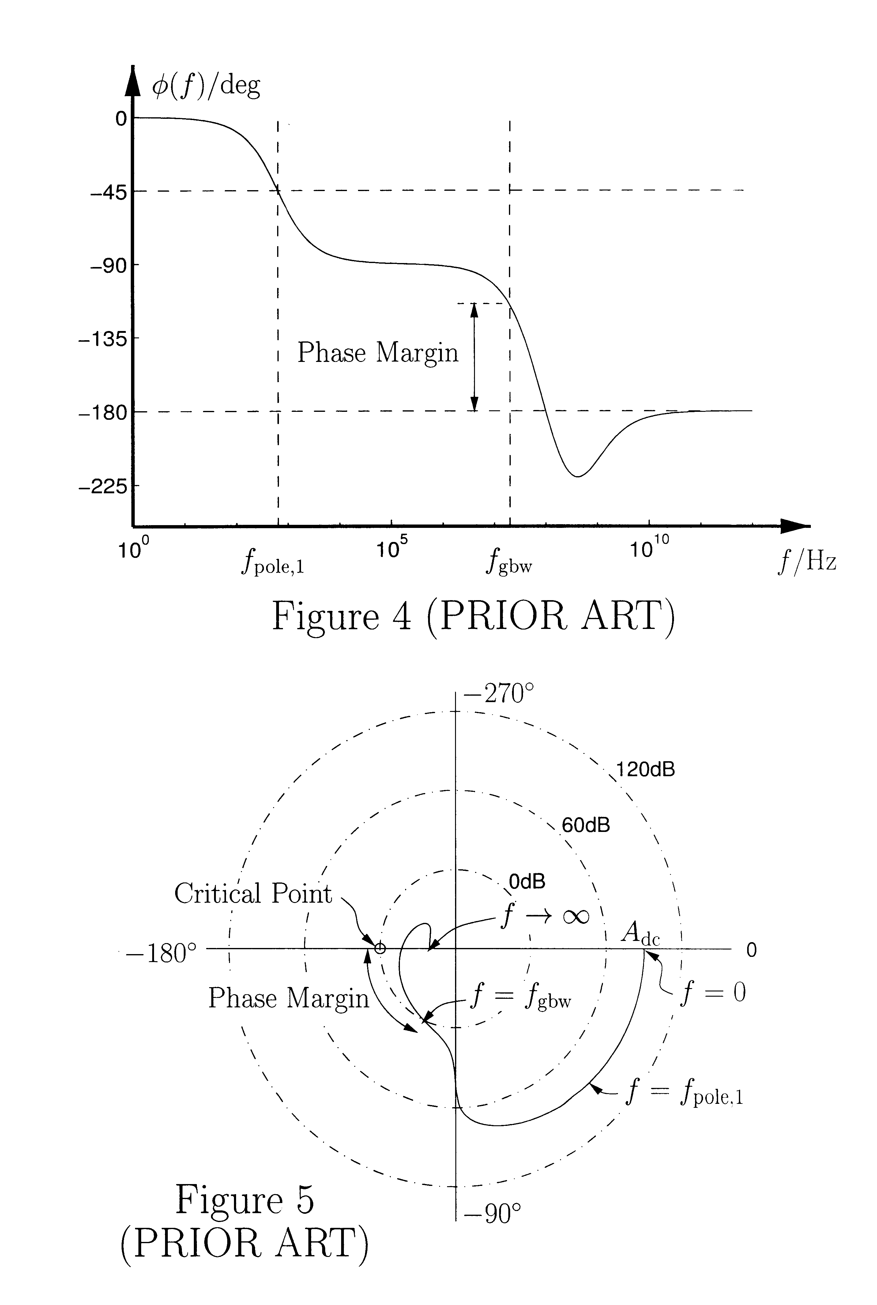
One of the difficulties in using non-ideal opamps is that the closed-loop system, e.g. the circuit shown in FIG. 2, may become unstable if the system's open-loop frequency response H.sub.OL (s) is not properly designed.
It is unavoidable that stray capacitors will make the angle .phi.
Because the transconductance g.sub.m cannot be made arbitrarily high (for a limited power / current consumption), this type of opamp provides only relatively little static gain when driving a resistive load [48].
However, opamps are generally quite nonlinear.
The output stage is particularly nonlinear because it will exhibit a large voltage swing, and especially if it has to provide a large current to the load.
This is very hard to achieve.
Considering that the capacitive load generally is quite large, it will be understood that drivers for ADSL modems are a very challenging design problem.
Another significant problem inherent to most opamps is that errors caused by the first stage are not suppressed at all.
In the extreme case, the input stage [54] will saturate, which results in slew-rate distortion.
Clearly, the multi-stage structures shown in FIGS. 9 and 10 do not ease the requirements to the input stage because the voltage across the compensation capacitors will vary synchronously with the output voltage, thus requiring all the transconductance stages to provide current signals proportional to the signal frequency and magnitude.
A fundamental difficulty of designing opamps is that the optimization of the input stage's linearity, the minimization of the opamp's noise and power consumption, and the maximization of the unity-gain frequency are conflicting requirements.
The conclusion is that it is difficult to achieve good external linearity at high signal frequencies.
On the other hand, if the unity-gain frequency, and thus the gain, is emphasized the linearity will be poor and relatively more gain needed to achieve the required level of external linearity.

Method used


Image

  • Wide-bandwidth operational amplifier
  • Wide-bandwidth operational amplifier
  • Wide-bandwidth operational amplifier

Examples


Embodiment Construction

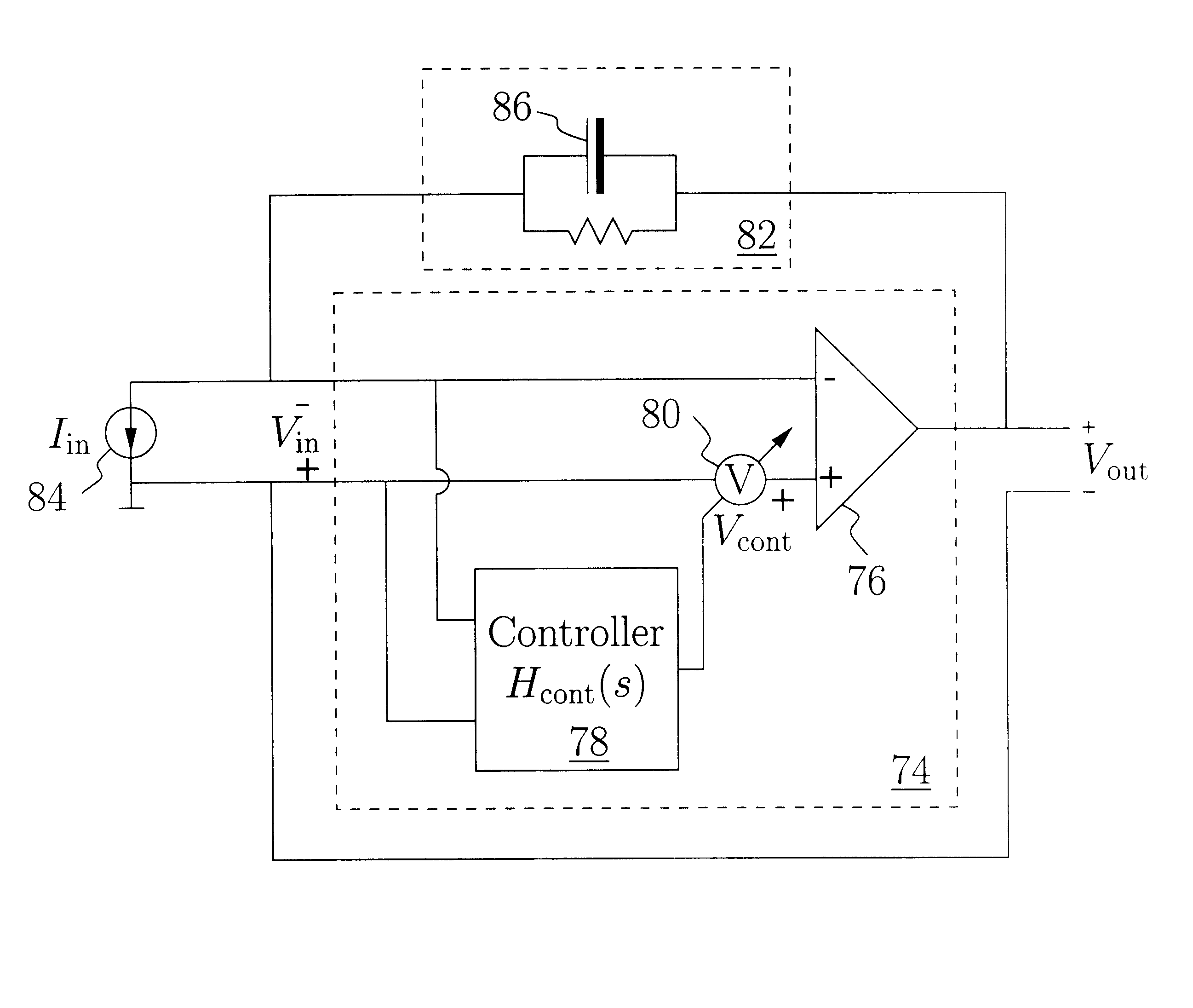
The fundamental idea of a first aspect of this invention is the same as that of noise-shaping delta-sigma loops: instantaneous errors in the output signal are acceptable provided that the signal-band power of the error signal is negligible. Hence, it is meaningful to consider the proposed opamp circuits to be "distortion-shaping" opamps. FIG. 12 illustrates the basic concept of a distortion-shaping opamp [74]. The distortion-shaping opamp [74] consists of a traditional opamp [76], a controller [78], and a mechanism to control the driving opamp's [76] offset, here represented by an offset regulator [80]. The distortion-shaping opamp [74] is intended for use in a negative-feedback configuration, which here is represented by an impedance element [82] and an input current source [84]. Hence the ideal transfer function V.sub.out (s) / I.sub.in (s) is similar to that of the circuit shown in FIG. 2.

The operation is as follows. The driving opamp [76] will, as any opamp in a stable negative-fe...


PUM


Abstract

An operational amplifier (opamp) [74] coupled in a negative-feedback configuration [82] [84] comprising a driving opamp [76]; a linear controller [78]; and a mechanism [80] controlling the driving opamp's [76] offset. A voltage signal Vin provided by the feedback network [82][84] characterizes all errors caused by the driving opamp [76]. The controller [78] monitors this voltage and minimizes the signal-band spectral components thereof by inducing an offset in the driving opamp [76]. The offset control mechanism [80] has approximately constant gain and only little phase delay in the signal band. The controller [78] may be a linear high-order Chebychev filter providing substantial gain in a wide frequency range, thereby efficiently suppressing all signal-band errors, including noise, harmonic distortion, and slew-rate errors, caused by the driving opamp [76]. The controller's [78] frequency response can be designed essentially independently of the feedback network's [82][84] feedback factor.The operational amplifier [74] is a general-purpose circuit. Important applications include video amplifiers and current-to-voltage conversion for asynchronous-digital-subscriber-line (ADSL) moderns.

Description

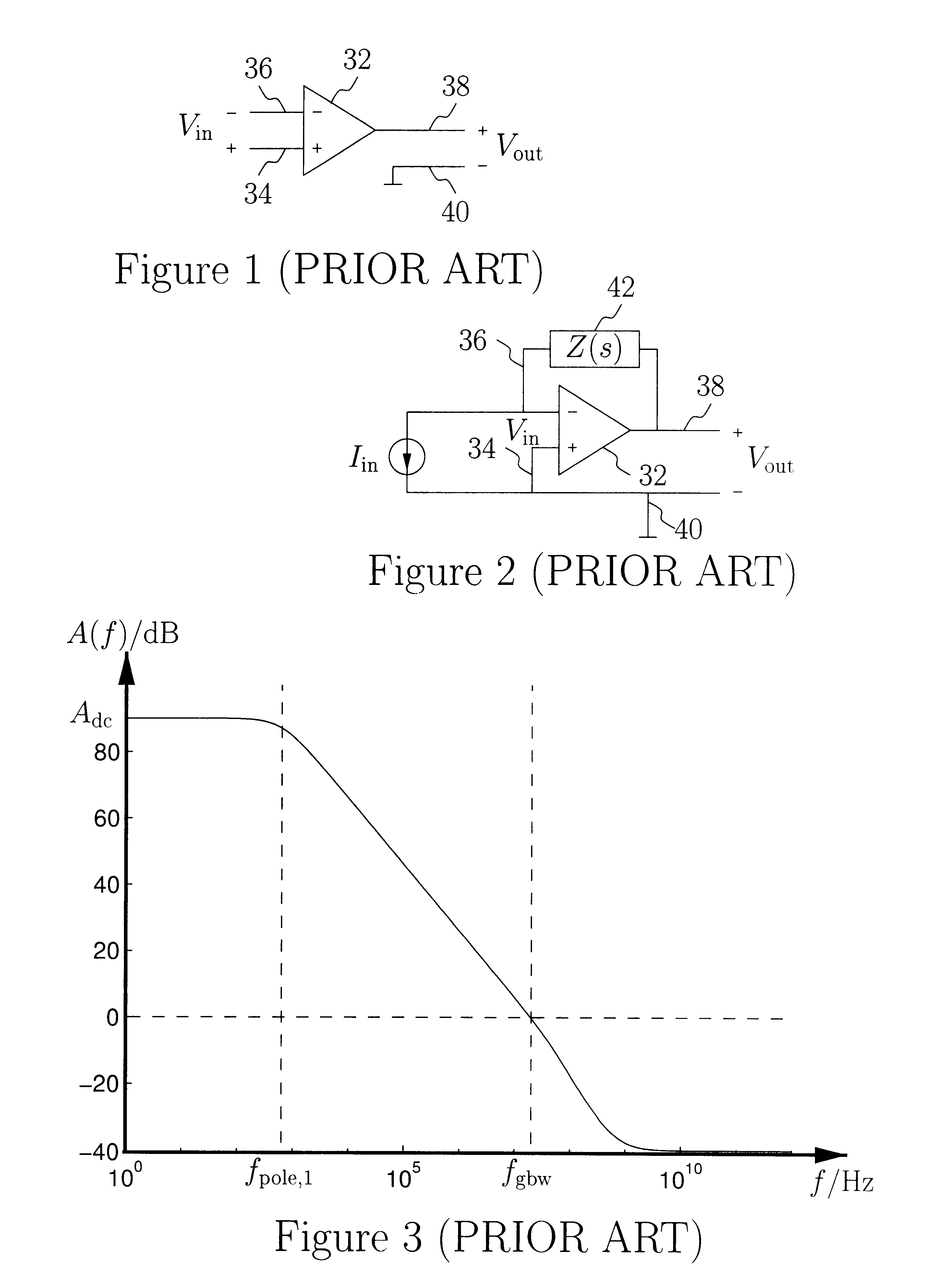
2 FIELD OF INVENTIONThe field of invention is analog electrical circuits, more particularly, this invention relates to operational amplifiers with increased gain in a wide bandwidth.3 DESCRIPTION OF PRIOR ARTAn operational amplifier, hereinafter referred to as an "opamp," is a general building block used in numerous analog electrical circuits. The symbol used to represent a general-purpose opamp [32] is shown in FIG. 1. A differential-input single-ended-output opamp [32] has a non-inverting input terminal [34], an inverting input terminal [36], and an output terminal [38], the voltage V.sub.out of which is defined with respect to a ground terminal [40]. In the ideal case, the two input terminals [34] and [36] are high-impedance terminals, i.e., they do not conduct any current, and the output voltage V.sub.out is a factor of A higher than the differential input voltage V.sub.in, where the gain A approaches infinity. In principle, the output voltage V.sub.out will depend only on the v...

Claims


Application Information

Patent Timeline
IPC IPC(8): H03F1/48H03F1/08H03F1/42H03F3/45H03F1/32
CPCH03F1/083H03F1/3211H03F1/3258H03F1/483H03F3/45475H03F3/45659H03F3/45197H03F2200/39H03F2200/331
Inventor STEENSGAARD-MADSEN, JESPER
Owner ANALOG DEVICES BV
Learn More