System and method for creating customizable nodes in a network diagram

a network diagram and customizable technology, applied in computing, instruments, electric digital data processing, etc., can solve the problems of not allowing filtering of nodes or displaying certain, and conventional art typically does not allow individual nodes to be formatted

Inactive Publication Date: 2009-10-13
MICROSOFT TECH LICENSING LLC
View PDF17 Cites 23 Cited by
  • Summary
  • Abstract
  • Description
  • Claims
  • Application Information

AI Technical Summary

Benefits of technology

[0019]The ‘Cell Layout’ dialog box can provide an interface for the selection of the number of rows and columns within for a cell layout of a particular data template. The ‘Cell Layout’ dialog box can further provide a selection for customizing cell width and how blank cells are displayed within a node.
[0020]According to another aspect of the invention, the ‘Box Style’ dialog box can also permit the selection of options for a highlight filter. In other words, a user can select a highlight style that can distinguish a set of nodes from other nodes in a network diagram. This highlight style can be merged with a node's regular category style settings to create merged formatting settings that are applied to nodes of a category that are designated to be highlighted. The “merging” of formatting settings in one embodiment can occur when highlight filter settings (that have a value) override the respective category settings. The result is that “highlighting” of nodes allows filter-matching nodes to be displayed with a certain set of similar characteristics. And the more highlight filter formatting options that have a value specified, the more alike the highlighted nodes from different categories will appear. When the highlight filter option in the ‘Box Style’ dialog box has been selected, a preview of the merged settings of the highlight filter formatting and a selected node category's formatting can be displayed.

Problems solved by technology

However, conventional PERT Chart program modules typically do not permit the filtering of nodes or displaying certain nodes based upon preset criteria.
Also, the conventional art typically does not permit individual node formatting.

Method used


Image

  • System and method for creating customizable nodes in a network diagram
  • System and method for creating customizable nodes in a network diagram
  • System and method for creating customizable nodes in a network diagram

Examples


Embodiment Construction

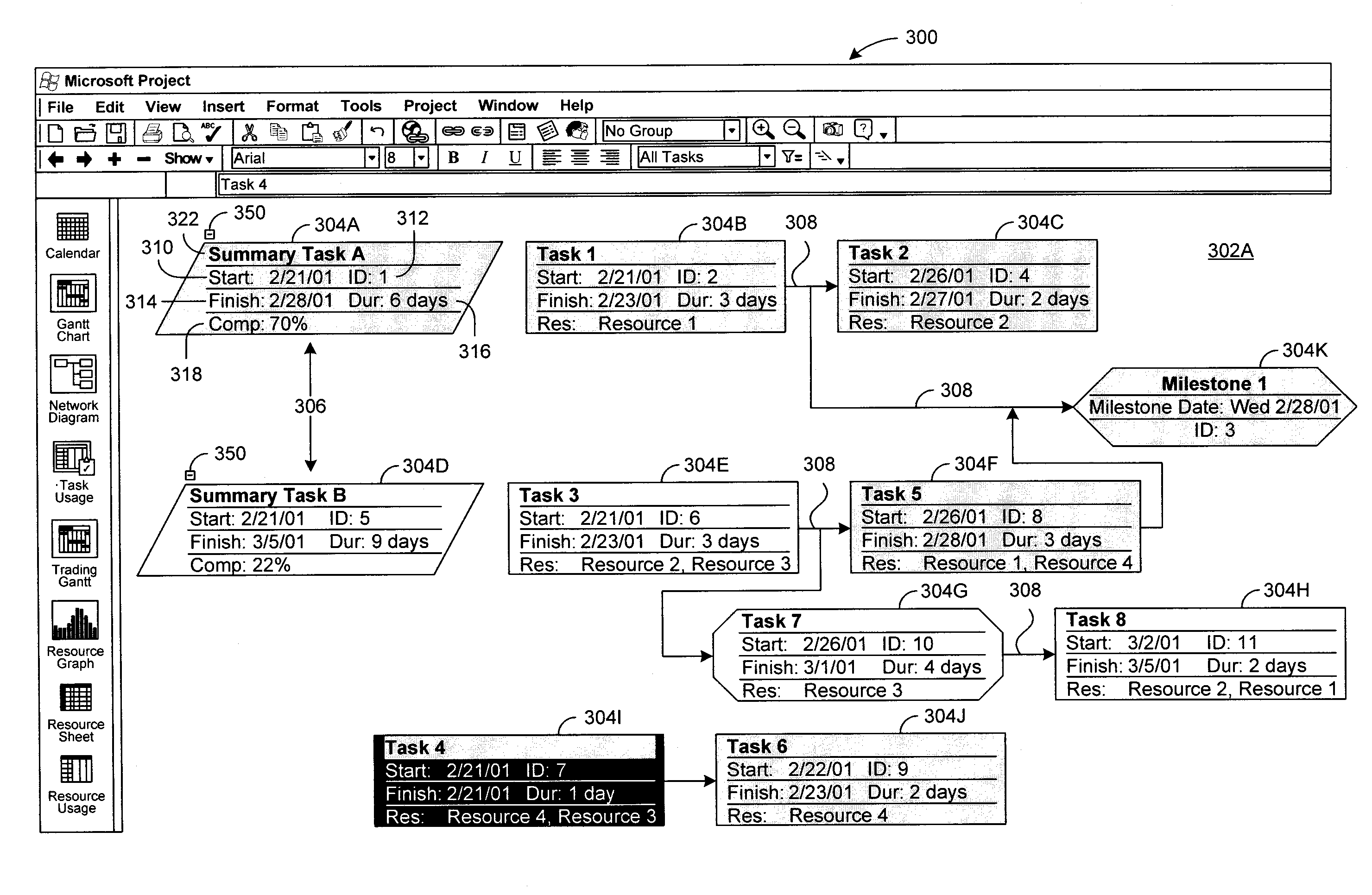
[0042]The system and method of the present invention organizes and generates a network diagram that permits the user to display one or more nodes at one magnification level while displaying other nodes at a different magnification level. The present invention further permits customization of shapes, sizes, and layout for data of nodes based upon node category or nodes selected by the user. The invention also provides a vehicle that permits a user to create his or her own data template for the layout of data within certain nodes. The invention further provides a formatting mechanism that is applied based on filtering that highlights nodes in a network diagram according to formatting parameters selected by a user. The invention can include a graphical user interface that permits rapid and easy selection of various formatting options for nodes displayed within a network diagram.

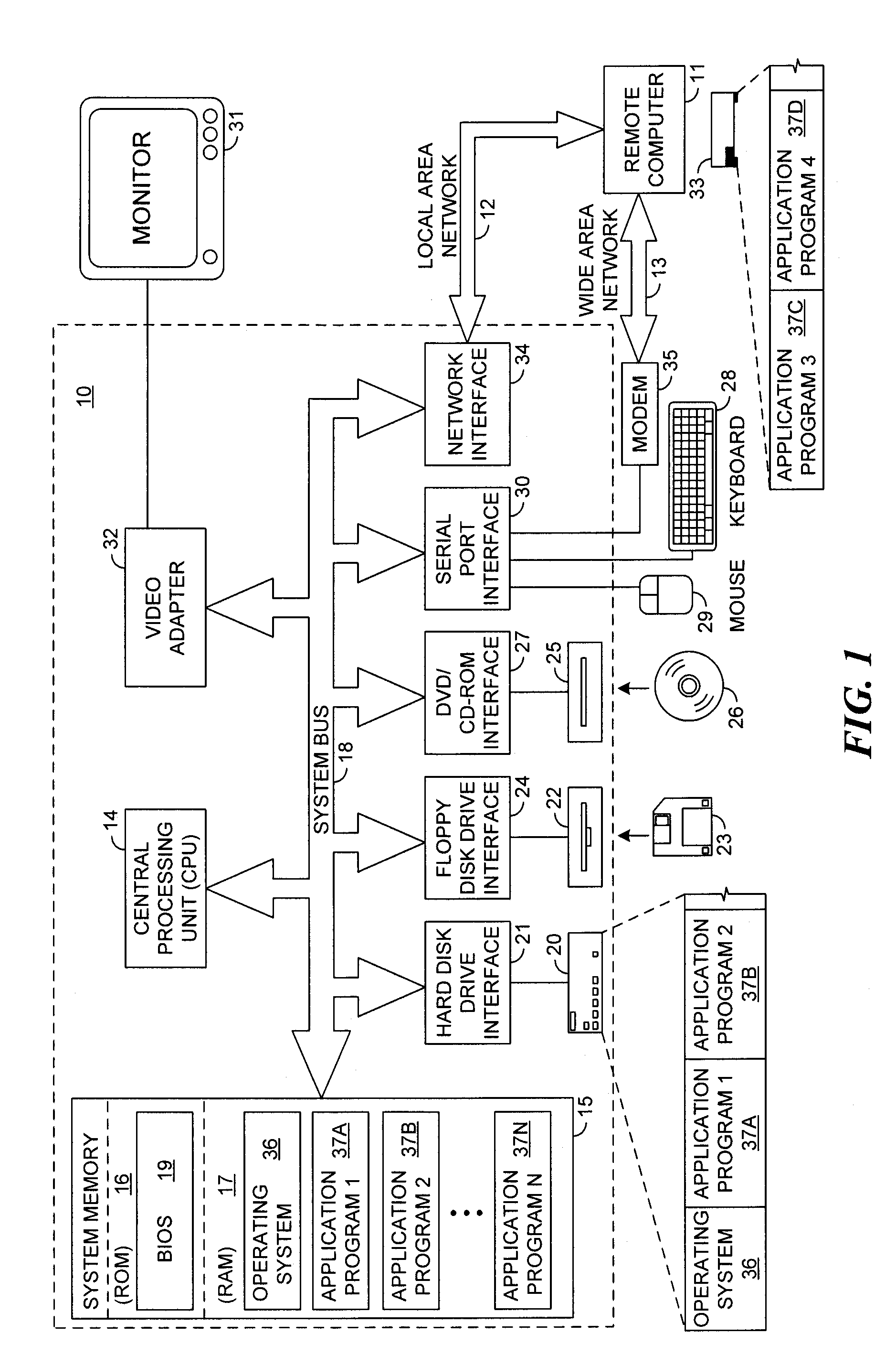
[0043]Although the preferred embodiment will be generally described in the context of a program and an operat...


PUM


Abstract

The present invention permits customization of shapes, sizes, and layout for data of nodes within a network diagram based upon node category or nodes selected by the user. The invention also permits a user to create his or her own data template for the layout of data within a certain category of nodes. The invention further provides a filter that highlights nodes in a network diagram according to parameters selected by a user. The invention can include a graphical user interface that permits rapid and easy selection of various options for nodes displayed within a network diagram. The system and method of the present invention also organizes and generates a network diagram that permits a user to display one or more nodes at one magnification level while displaying other nodes at a different magnification level.

Description

CROSS REFERENCE TO RELATED APPLICATION[0001]This application is related to U.S. patent application Ser. No. 09 / 703,756 filed Nov. 1, 2000, entitled “System and Method for Creating a Customizable Network Diagram”TECHNICAL FIELD[0002]The present invention relates to computer systems for generating charts and graphs. More particularly, the present invention relates to computer systems that create network diagrams comprising nodes that can be customizable by a user.BACKGROUND OF THE INVENTION[0003]Many conventional project planning software applications provide multiple chart formats for project scheduling data. However, the conventional project planning software applications do not typically permit customization of the elements that define a work chart.[0004]For example, the simplest scheduling tool is the bar or Gantt chart. In this conventional format, work activities or tasks are listed in a vertical direction while elapsed time for each work activity or task is recorded horizontall...

Claims


Application Information

Patent Timeline
Patent Type & Authority Patents(United States)
IPC IPC(8): G06F3/048G06Q10/00G09G5/00
CPCG06F3/0482G06Q10/00G06F2203/04805
Inventor AAMODT, JEFFREY R.SOUROV, ALEXANDER A.SNAPKAUSKAS, DARIUS
Owner MICROSOFT TECH LICENSING LLC
Why Eureka
Try Eureka