Method and apparatus for optical mode division multiplexing and demultiplexing

a technology of optical mode and multi-mode, applied in the field of integrated optics, can solve the problems of poor separation between the divided modes, the sensitivity of fabrication parameters, and the difficulty of coupling modes residing in different waveguides, and achieve coupling and/or cross talk between modes

Inactive Publication Date: 2009-10-27
NEOPHOTONICS CORP
View PDF26 Cites 9 Cited by
  • Summary
  • Abstract
  • Description
  • Claims
  • Application Information

AI Technical Summary

Benefits of technology

[0003]Embodiments of the present invention provide an apparatus and method of transferring a signal from a mode of one waveguide to a mode of another waveguide substantially without affecting other modes of the waveguides.
[0004]In accordance with some exemplary embodiments of the invention, there is provided an apparatus to transfer a signal from a first mode of a first waveguide to a second mode of second waveguide, the apparatus including a mode interaction region associated with mutually proximal regions of the first and second waveguides, wherein the signal carried by the first mode of the first waveguide is transferred to the second mode of the second waveguide without significantly affecting any other signal carried by any other mode of the first and second waveguides.

Problems solved by technology

Among the drawbacks of this solution are its sensitivity to fabrication parameters and a difficulty in coupling modes residing in different waveguides.
The drawbacks of this solution include the critical manufacturing tolerances of the device, and the poor separation between the divided modes leading to coupling and / or cross talk between the modes.
A further known way to achieve mode-conversion is using a multi-mode interference converter; however, this solution has low conversion efficiency.

Method used


Image

  • Method and apparatus for optical mode division multiplexing and demultiplexing
  • Method and apparatus for optical mode division multiplexing and demultiplexing
  • Method and apparatus for optical mode division multiplexing and demultiplexing

Examples


Embodiment Construction

[0018]In the following detailed description, numerous specific details are set forth in order to provide a thorough understanding of the invention. However, it will be understood by those of ordinary skill in the art that the present invention may be practiced without these specific details. In other instances, well-known methods, procedures, components and circuits may not have been described in detail so as not to obscure the present invention.

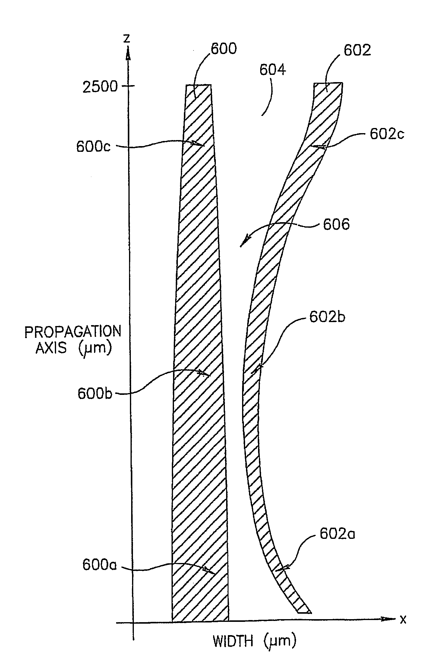
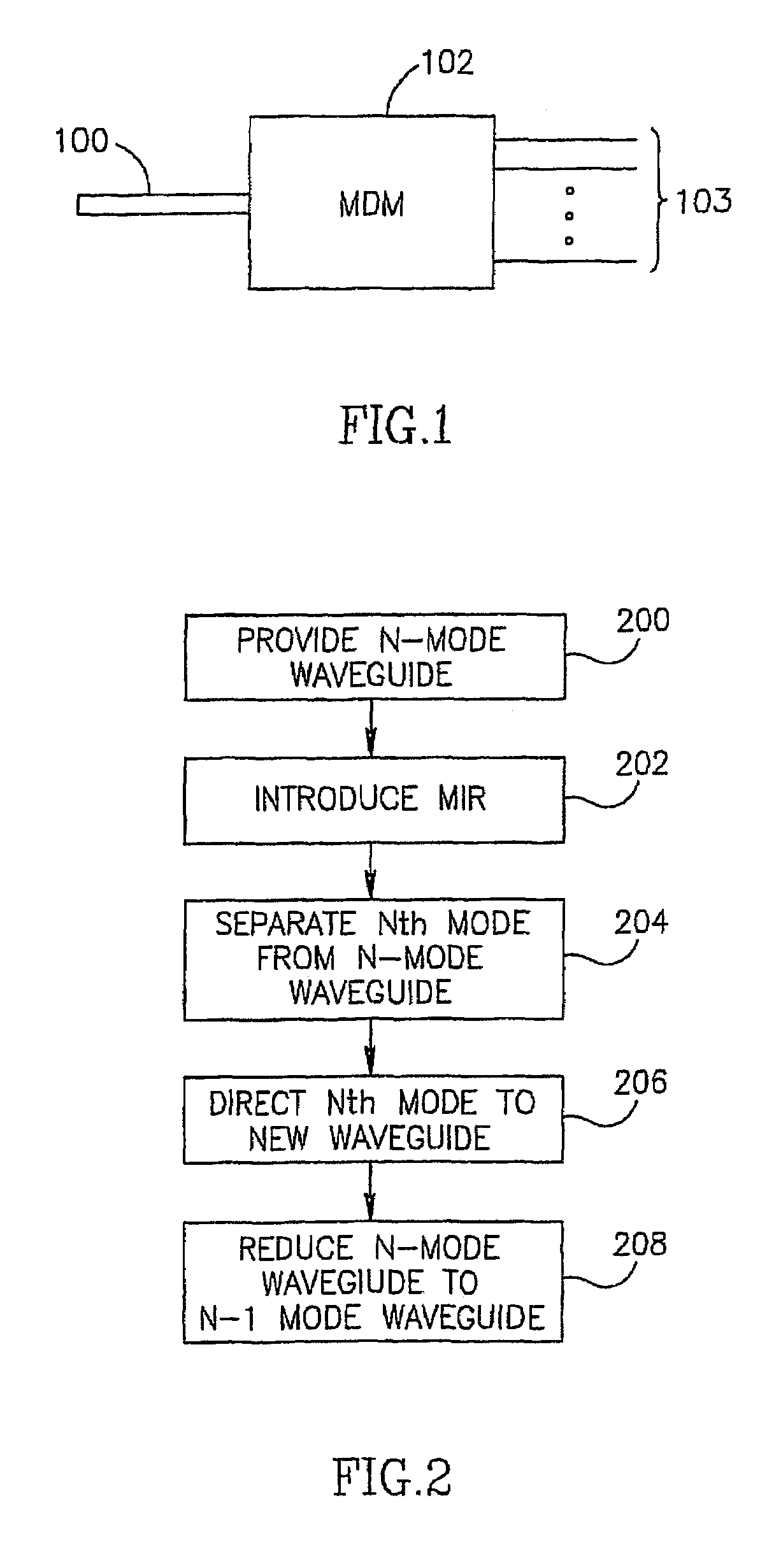
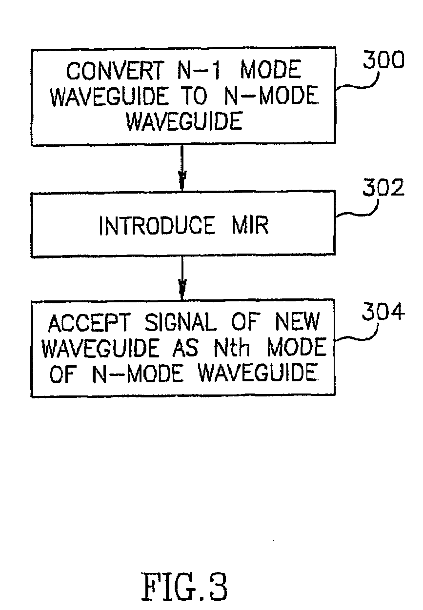
[0019]Embodiments of the present invention enable mode division multiplexing and demultiplexing. In mode division multiplexing in accordance with embodiments of the invention, signals from a given number, N, of single-mode (SM) waveguides may be combined into a multi-mode signal carried by single N-mode multi-mode (MM) waveguide, wherein each order mode carries a signal associated with a particular one of the SM waveguides. In mode division demultiplexing in accordance with embodiments of the invention, the N signals from a single N-mode mul...


PUM


Abstract

A method of mode selective coupling or mode multiplexing between integrated multimode (600) and single mode (602) waveguides. Evanescent coupling and tapering is used so that the signal may be transferred adiabatically from a first region of a first waveguide to a second, proximal, region of a second waveguide.

Description

CROSS-REFERENCE TO RELATED APPLICATIONS[0001]This application is a National Phase Application of PCT International Application No. PCT / IL03 / 00443, International Filing Date May 28, 2003, claiming priority of U.S. Provisional Patent Applications, 60 / 383,325, filed May 28, 2002, and 60 / 383,326, filed May 28, 2002BACKGROUND OF THE INVENTION[0002]In the field of integrated optics, there may be a need to transfer a signal carried by one waveguide, for example, a single-mode wave-guide, to another waveguide, for example, a multi-mode waveguide, where the signal may be carried by one of a plurality of modes, each of a different order, or vice versa. One known way of doing so includes establishing a periodic perturbation using a static device designed to provide long period grating in the multimode waveguide, thereby to couple co-propagating modes. Among the drawbacks of this solution are its sensitivity to fabrication parameters and a difficulty in coupling modes residing in different wave...

Claims


Application Information

Patent Timeline
Patent Type & Authority Patents(United States)
IPC IPC(8): G02B6/26G02B6/12G02B6/122G02B6/125
CPCG02B6/12007G02B6/1228G02B6/14G02B6/125G02B2006/12147
Inventor NAREVICIUS, EDVARDAS
Owner NEOPHOTONICS CORP
Why Eureka
Try Eureka