Supercharge Your Innovation With Domain-Expert AI Agents!

Apparatus to produce spectrums

a spectrum and apparatus technology, applied in the field of apparatus to produce spectrums, can solve the problems of difficult to find a device that will work with readily available equipment, few of these devices will work with the other products needed, and most of the available spectrum equipment is out of the reach of ordinary people's budgets, so as to achieve the effect of compact spectrum

Inactive Publication Date: 2009-10-27
BROWN ROGER WAYNE
View PDF15 Cites 0 Cited by
  • Summary
  • Abstract
  • Description
  • Claims
  • Application Information

AI Technical Summary

Problems solved by technology

Finding a device that will present a lot of the information contained within a spectrum of an object and one that will work with readily available equipment is difficult.
However, few of these devices will work with the other products needed to produce, store and retrieve a spectrum's information.
This leaves most of the available spectrum equipment out of the reach of ordinary people's budgets.
The quality of the spectrum devices available to the last group is severely lacking in spectral detail, available tool sets, compatibility and instruction to use the various components of the system required to capture an object's spectrum.
A typical system, for an individual that desires detailed spectral line information, is to buy one of the SBIG CCD cameras at a cost of several thousand dollars then for an additional cost of several thousands of dollars add a spectrum device that will work only with that camera, but these two items alone aren't sufficient to detail a spectrum so the list goes on and the price tag approaches the tens of thousands of dollars and all just to produce the picture of a small colored line from a bright object.
The cost continues to go up as the object becomes dimmer.
This cost is prohibitive for most prospective users and few schools and colleges can spend this level of money for equipment that has such a narrow field of use.
Their device is sold with a cylindrical lens that is used to make the spectrum visually taller but this attachment won't work when attached to a camera as this attachment is strictly for visual use.
Their unit will not work with cameras made by other manufacturers or with most of their other cameras.
Their device is incapable of producing a referenced spectrum.
This is because it is mounted too far from the sensor.
The spectrum their units produce can't be used with dim stars as their spectrum is so tall with their cylindrical lens that its intensity quickly falls below the threshold of light sensors and other capture devices.
Using a cylindrical lens with these devices will also distort the image of the spectrum as well as greatly reduce its intensity.
A major problem with using these two devices on a CCD camera is that because they use a 200 lines / mm grating the spectral image is exceedingly small on the CCD chip, usually covering less than 20% of the chips width.
Such small use of the chip results in extremely low resolution spectrums with little to no contained information content.
Another major drawback with their product is that they both use a blazed grating.
This greatly reduces the bandwidth of their devices which is generally limited to 420 nm to 670 nm.
The bandwidth of most inexpensive CCD cameras extends from 390 nm to over 950 nm so using a blazed grating with these cameras greatly reduces the bandwidth gain these cameras are capable of producing.
Another drawback with using blazed gratings is the spectrums they produce are bell shaped, with respect to intensity versus wavelength efficiency, instead of producing flat spectrums as is generated by non-blazed gratings.
This makes calibration of the spectrum blazed gratings produce very difficult.
One of the many objections users have with devices from these two companies is that their devices are designed strictly for visual use and as such it is extremely difficult to adapt them to work on a CCD camera.
Their units were only designed to be used with a threaded telescope eyepiece and they don't offer any adapters to fit most CCD cameras, and neither of these two companies offer any device that is designed to fit inside the lens housing of a camera or offer a devise designed to fill the film plane or CCD chip of a camera.
Because of the course grating that they both use in their devices the spectrums produced are of little value due to the low resolution available with course gratings, and it is extremely difficult to resolve and identify individual spectral lines with their devices which is the main purpose of capturing an object's spectrum.
The device sold by SBIG is priced far too high to bring it into general use.
While this device does produce photographable spectrums of good resolution it doesn't perform well with dim stars due to the extra light loss within their system.
While their device does produce a high quality spectrum, it does not produce a reference spectrum and requires a very complicated means to determine the spectrum's wavelength information.
They do not offer Angstrom level referencing or calibration tools with their unit and leave this complicated task to the user to solve on their own.

Method used


Image

  • Apparatus to produce spectrums
  • Apparatus to produce spectrums
  • Apparatus to produce spectrums

Examples


Embodiment Construction

Overview

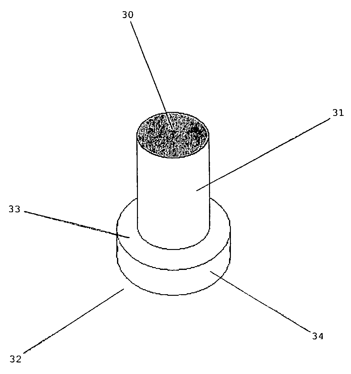
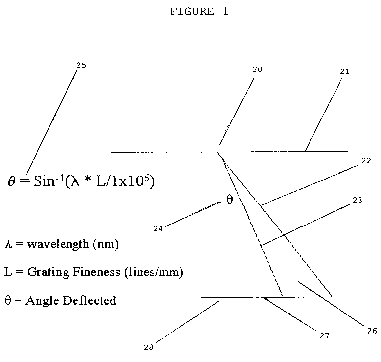
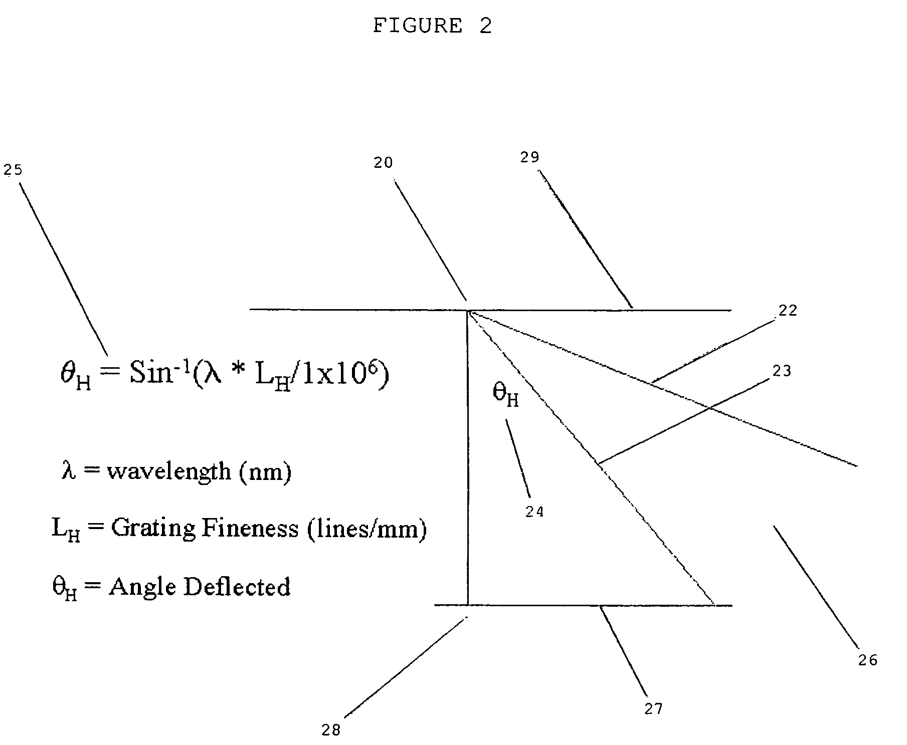
[0045]By fabricating the spectrum 26 separation device in such a manner that it will fit within the confines of the empty lens chamber, just in front of the sensor 27, of an available camera will provide a means to produce high quality referenced spectrums with little or no additional cost for other expensive equipment as is generally required.

[0046]The selection of a spectrum 26 device lends itself readily to using a grating 30 type of spectrum 26 device. These are generally easier to manufacture and are generally lighter in weight then are prism devices thereby reducing cost of manufacturer.

[0047]In order for any spectrum 26 device to provide the maximum amount of information the distance between itself and the light sensor 27, be it film, the human eye, or a CCD chip or anything else that is sensitive to light of any wavelength in the visible, ultraviolet and or infrared, is very critical.

[0048]In current technology the distance between the spectral device and the light s...


PUM


Abstract

A method of placing a grating material at an optimum distance from a sensor that will produce a reference spectrum on that sensor. In a preferred embodiment of the present invention, a device with a diffraction grating end will protrude into the empty lens well of a camera and with the camera inserted into a telescope eyepiece holder will focus both a image of an object, that the telescope is pointed to, and its spectrum onto the light sensor in the camera. This dual image, called a reference spectrum, allows the separation between the image of the object and a point in the image of its spectrum to be determined quickly. This separation distance to the spectral point within the spectrum is then a referenced distance. Once a reference distance is known it is then used to determine the wavelength of any other point or spectral line within the spectrum.

Description

RELATED APPLICATIONS[0001]This application claims priority on provisional application No. 60 / 698,045 filed Jul. 12, 2005, and Disclosure Document number 580,157 filed Jun. 15, 2005.[0002]The present application is related to U.S. Pat. No. 6,813,018, issued Nov. 2, 2004, for HYPERSPECTRAL IMAGER, by Richman, included by reference herein.[0003]The present application is related to U.S. Pat. No. 6,549,280, issued Apr. 15, 2003, for SPECTROMETER WITH DOUBLE OFF-AXIS SCHMIDT TELESCOPE, by Riccardo, et. al., included by reference herein.[0004]The present application is related to U.S. Pat. No. 6,304,324, issued Oct. 16, 2001, for METHOD OF CALCULATING OPTICAL FREQUENCY SPECTRUM, by Iwasaki, included by reference herein.[0005]The present application is related to U.S. Pat. No. 4,805,990, issued Feb. 21, 1989, for APPARATUS FOR VIEWING A REFRACTED IMAGE AND PHOTOGRAPHIC METHOD, by Edwards, included by reference herein.[0006]The present application is related to U.S. Pat. No. 6,590,648, issu...

Claims


Application Information

Patent Timeline
Patent Type & Authority Patents(United States)
IPC IPC(8): G03B11/00
CPCG01J3/2803G01J3/00
Inventor BROWN, ROGER WAYNE
Owner BROWN ROGER WAYNE
Features
  • R&D
  • Intellectual Property
  • Life Sciences
  • Materials
  • Tech Scout
  • Unparalleled Data Quality
  • Higher Quality Content
  • 60% Fewer Hallucinations
Learn More