Pedicle screw for intervertebral support elements

a technology of intervertebral support elements and pedicle screws, which is applied in the field of stabilization of spinal columns, can solve problems such as difficulty in carrying ou

Inactive Publication Date: 2009-11-03
ZIMMER GMBH
View PDF55 Cites 122 Cited by
  • Summary
  • Abstract
  • Description
  • Claims
  • Application Information

AI Technical Summary

Benefits of technology

[0004]The object of the present invention is to create, for dynamic vertebra supporting, a pedicle screw for intervertebral support elements for which the securing of the support element

Problems solved by technology

The drawing in of the band is an operati

Method used


Image

  • Pedicle screw for intervertebral support elements
  • Pedicle screw for intervertebral support elements
  • Pedicle screw for intervertebral support elements

Examples


Embodiment Construction

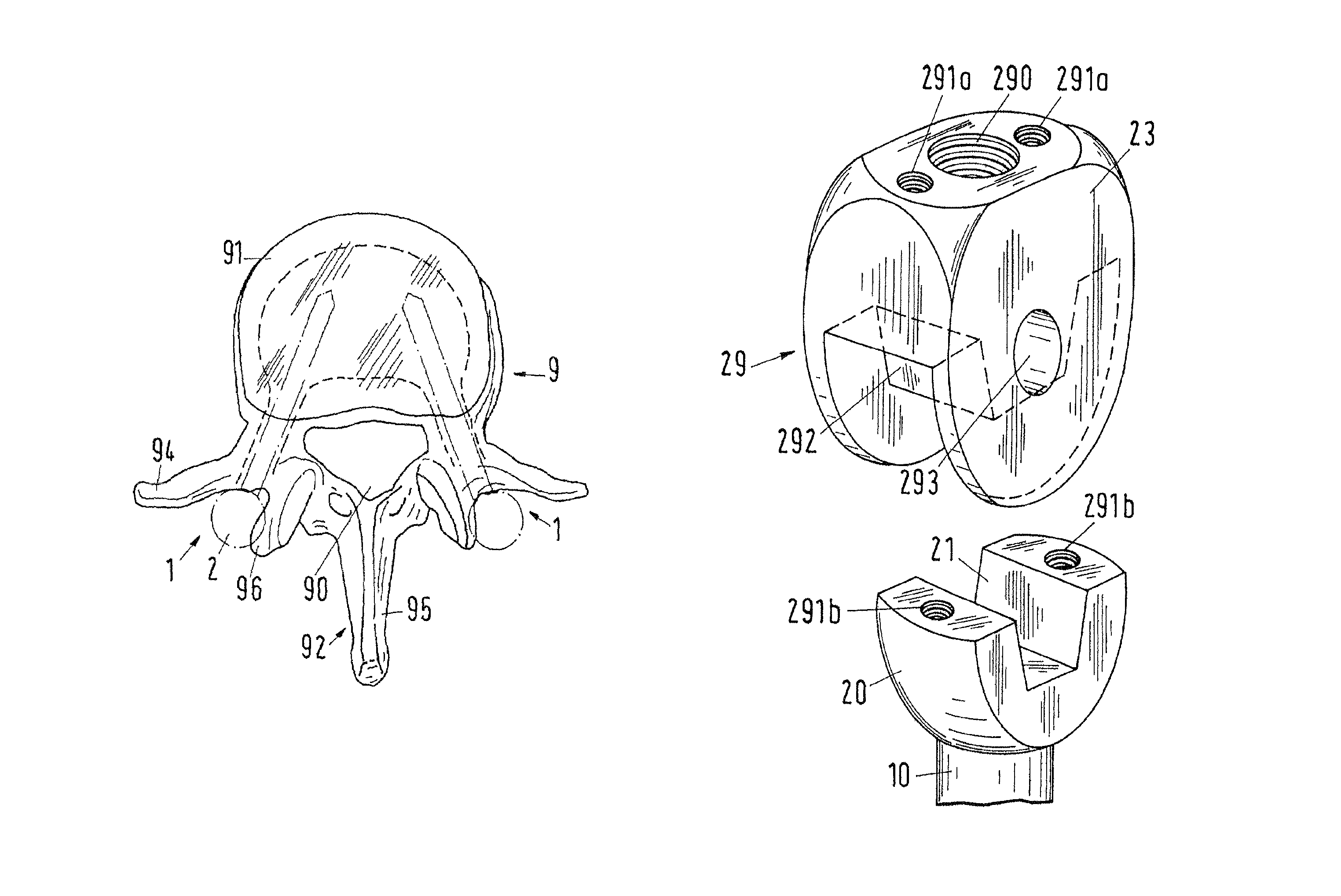
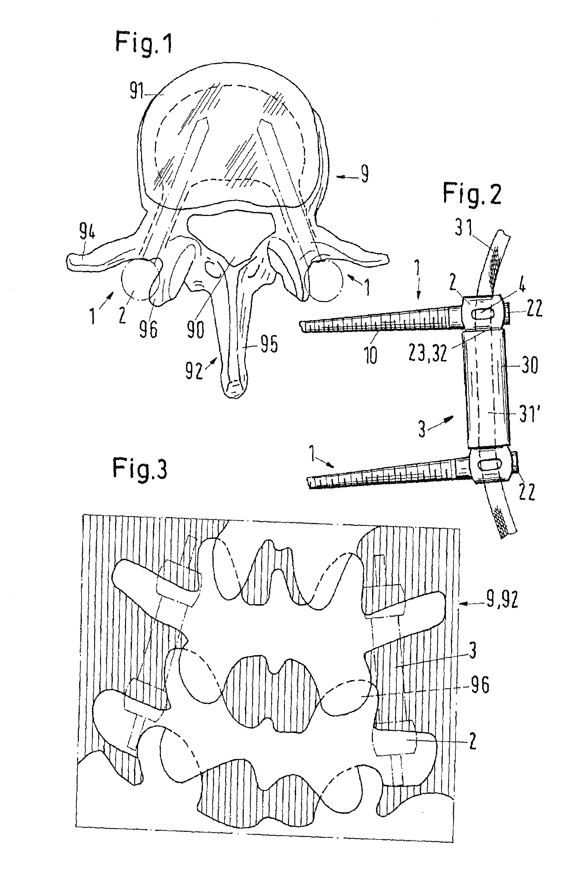
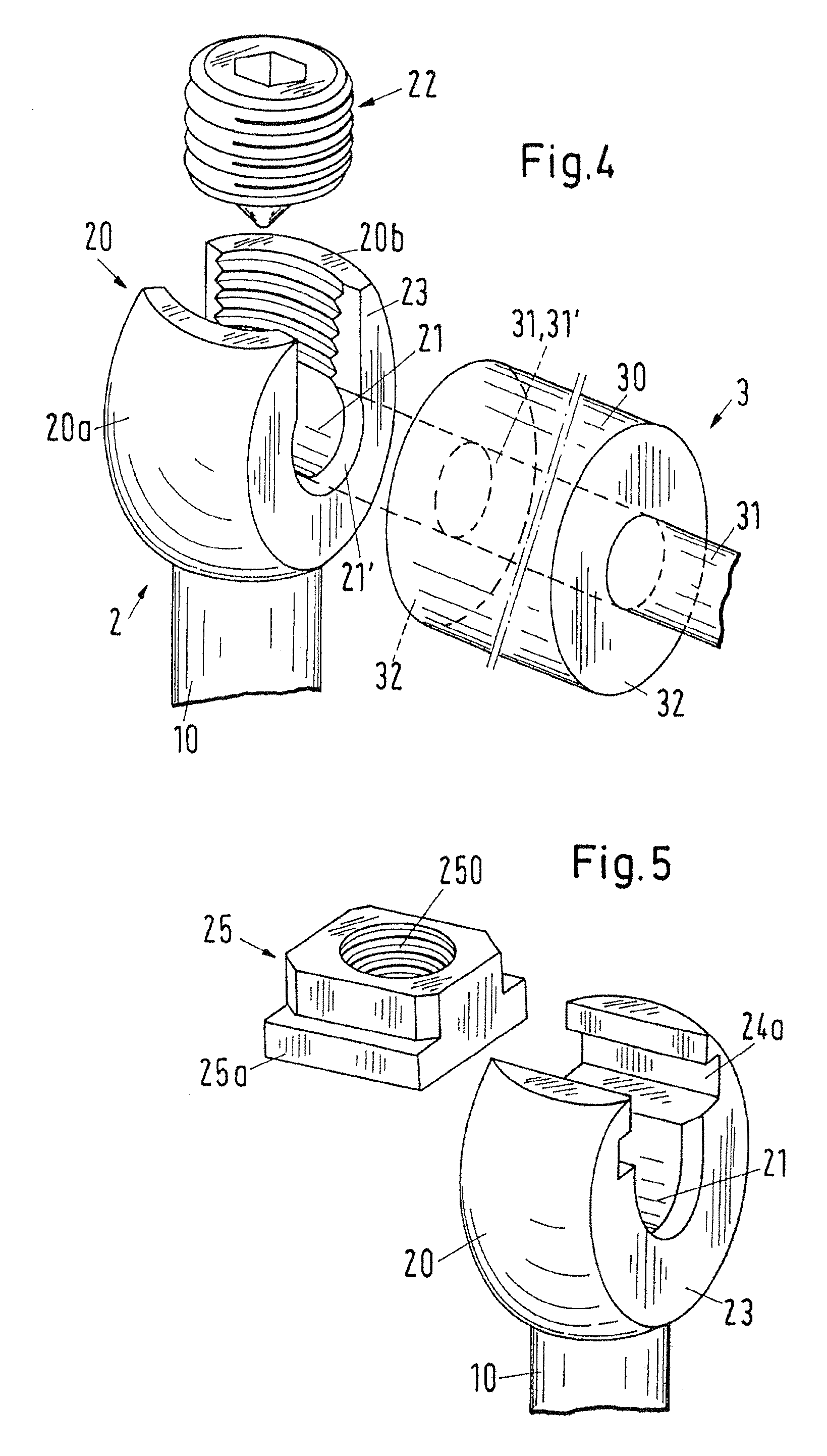
[0019]A lumbar vertebra 9 in accordance with FIG. 1 consists of a vertebral hole 90, a vertebral body 91 and a vertebral arch 92 which comprises two pedicles 93, two transverse processes 94, a spine 95 of a vertebra and articular processes 96. The positions of two pedicle screws 1 in the implanted state are indicated in chain-dotted lines. In these positions the heads 2 of the pedicle screws 1 are located directly at the outer side of the pedicles 93 between the transverse processes 94 and the articular processes 96. FIG. 2 shows two pedicle screws 1, which are provided for two adjacent vertebrae 9 and between the heads 2 of which, which are formed as rings, an intervertebral support element 3 is arranged. Shafts 10 of the pedicle screws 1 are screwed in into the vertebrae 9. The heads 2 have notches 4 laterally which are required for the implanting and orientation of the pedicle screws 1 by means of an instrument. The support element 3 consists of a piece of a cable-like band 31 an...


PUM


Abstract

The pedicle screw (1) for intervertebral support elements (3) consists of a shaft (10) and a head (2) comprising at least two parts (20, 22). The head is formed as a securing means for at least one support element (3). Each support element consists of a piece of a cable-like band (31) and a cylindrical support body (30) with an axial lumen (31′) containing the band. The band is securable outside end surfaces (32) of the support body in the head. The head is formed with a contact surface (23) via which a pressure stress can be exerted on the support body in the band direction, and indeed using the band and in cooperation with a further pedicle screw. A part (20) of the head (2), which is firmly connected to the shaft (10) at the one end of the latter, contains a base groove (21) which is oriented transversally to the shaft and into which the part of the band (31) to be secured or a connecting piece (292) which contains the band can be introduced during the securing of the support element (3) by means of a translatory movement in the direction of the shaft and fixed there.

Description

[0001]This is a continuation of U.S. application Ser. No. 09 / 956,055, filed Sep. 18, 2001; which claims priority to European Patent Application No. 00810845.8, filed on Sep. 18, 2000, which are all incorporated by reference herein.[0002]The invention relates to a pedicle screw for intervertebral support elements in accordance with the preamble of claim 1.BACKGROUND OF THE INVENTION[0003]Invasive treatment methods are known for the stabilization of spinal columns in which bone bridges are made to grow between adjacent vertebral bodies using implants. Stiffening fusions of the adjacent vertebrae result through the bone bridges. In addition to stiffening operations of this kind a treatment method for stabilizing by means of an implant system is also known in which no fusion arises, but rather a mobility is preserved between adjacent vertebrae. This implant system comprises pedicle screws and intervertebral support elements which are implanted during the operation from the back. Each pe...

Claims


Application Information

Patent Timeline
IPC IPC(8): A61F5/00A61B17/58A61B17/70
CPCA61B17/704A61B17/7032A61B17/7037A61B17/7031A61B17/7004A61B17/7005A61B17/7007
Inventor WALDER, RETOBRAUNSCHWEILER, RETO
Owner ZIMMER GMBH
Why Eureka
Try Eureka