Eureka AIR delivers breakthrough ideas for toughest innovation challenges, trusted by R&D personnel around the world.

Packaging unit with slidable casing

a casing and packaging technology, applied in the field of packaging units, can solve problems such as danger, and achieve the effects of reducing the width of the casing, and effective clamping force of the casing to the container

Active Publication Date: 2009-11-10
ROBERT BOSCH GMBH
View PDF13 Cites 36 Cited by
  • Summary
  • Abstract
  • Description
  • Claims
  • Application Information

AI Technical Summary

Benefits of technology

[0003]The packaging unit according to the present invention has the advantage that the clamping force, created at the section having the narrowed cross section, generates a friction locking between the container and the casing which is sufficient for preventing the slipping out of the container from the casing, when the packaging unit is held vertically. This minimizes the risk that the container slips out downwards when the retail customer takes down the packaging unit from the merchandise suspension mount, and that, in the process, the packaged item is damaged by falling.
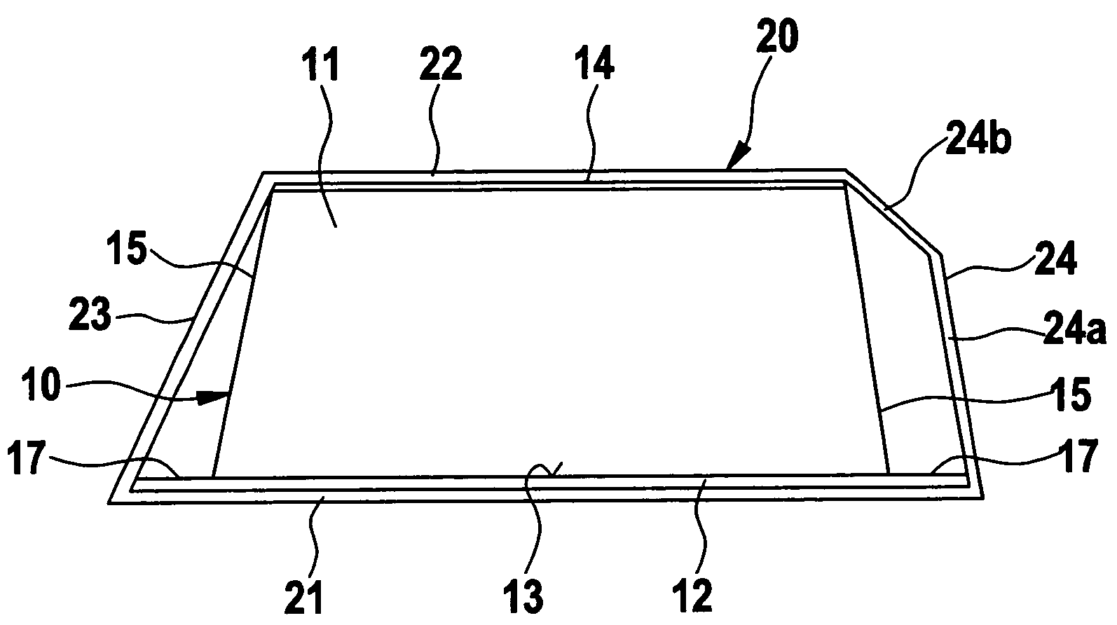
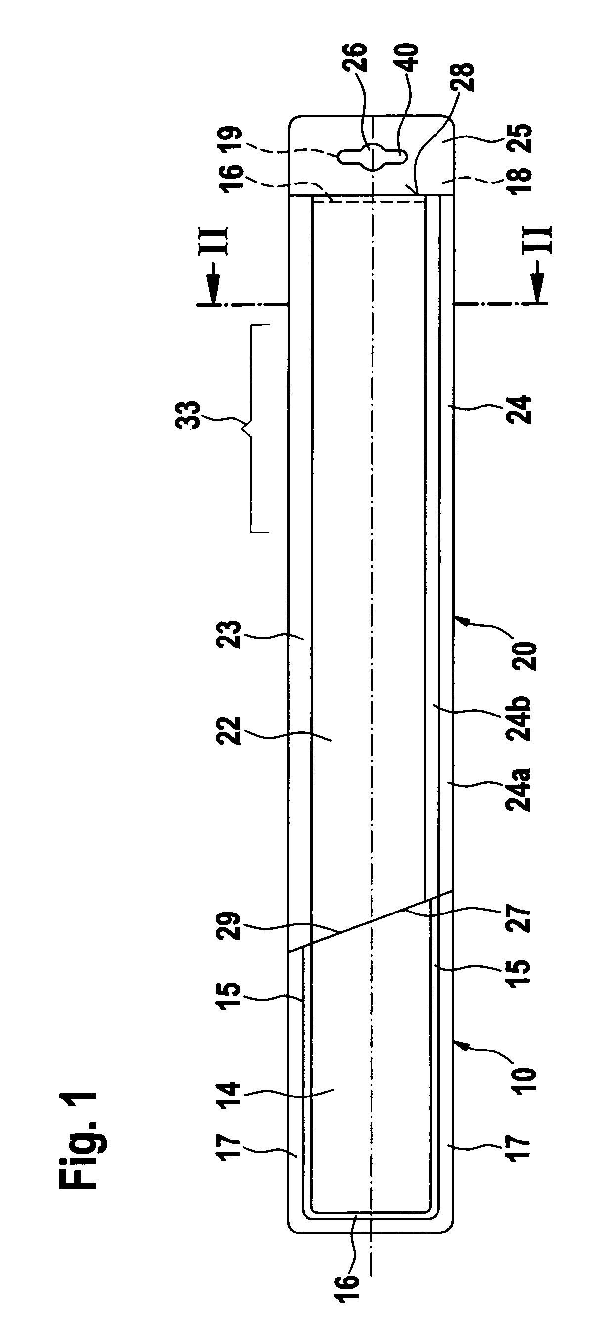
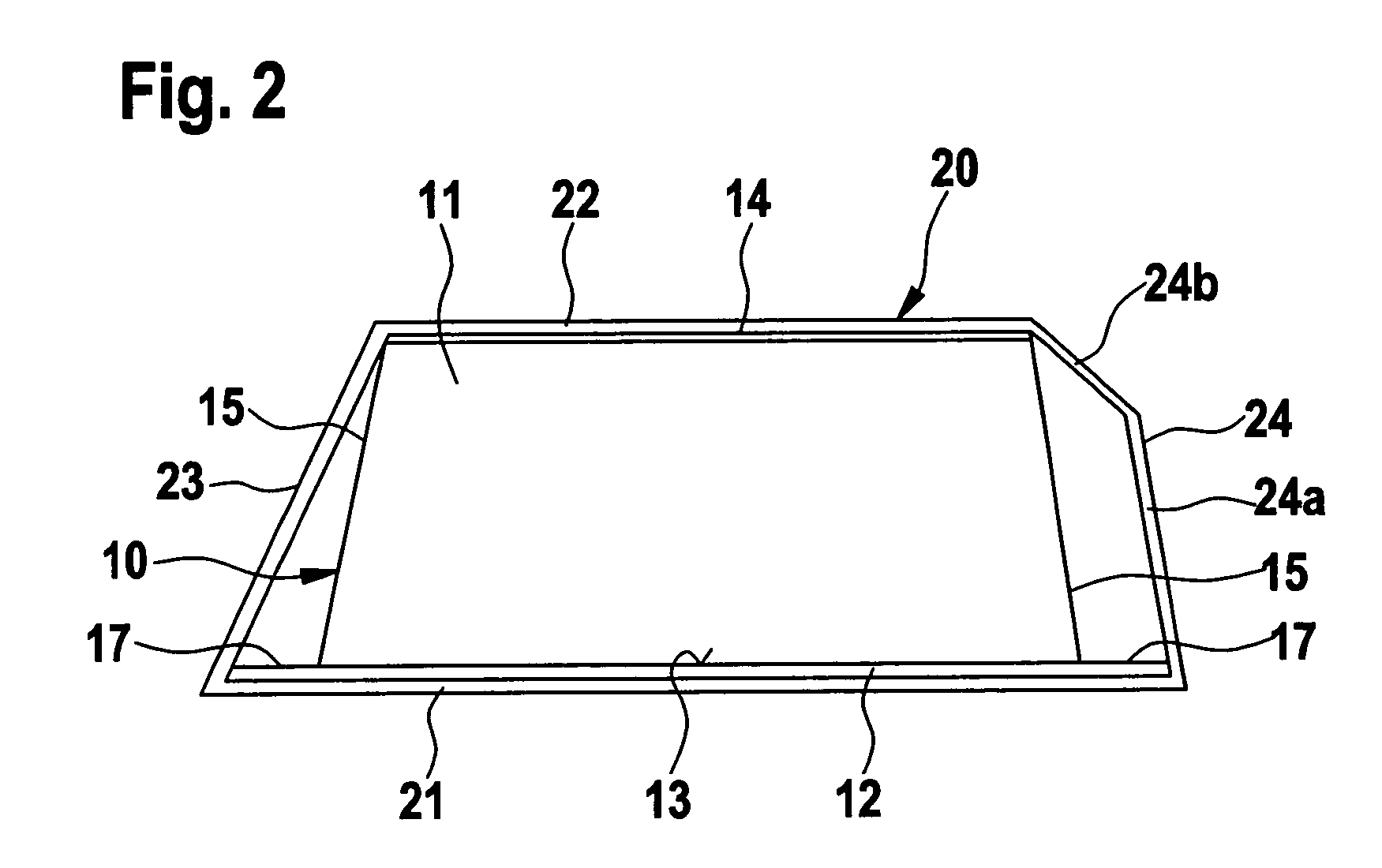
[0004]A particularly effective clamping force of the casing to the container is achieved if the section having the narrowed cross section is developed by reducing the width at the rear panel of the casing. The reduced width of the casing is advantageously produced at the punched blank in that the section having the reduced width at the rear panel is developed by a fold profile that deviates from a straight fold profile. The deviating fold profile is expediently developed at the fold opposite an adhesive surface, by a deviating or bent scoring of the punched blank in the area of the section having the narrowed cross section. In this context, the deviating fold profile has an extension that runs essentially parallel to the remaining fold profiles, which makes up, for instance, ⅓ to 1 / 10 of the total extension of the casing. It is also expedient if the section having the narrowed cross section or the reduced width of the casing is developed in the half of the casing that points towards an eyelet or opening for hanging it up. Because of that, there is created, in the direction towards the opening, a slightly widened cross section, which makes it easier to slide the container into the casing.

Problems solved by technology

This danger exists particularly when the retail customer grabs the packaging unit by the casing using little force, and hangs it up on, or takes it down from the merchandise suspension mount.

Method used


Image

  • Packaging unit with slidable casing
  • Packaging unit with slidable casing
  • Packaging unit with slidable casing

Examples


Embodiment Construction

[0008]The packaging unit shown in FIGS. 1 and 2 is made up of a container 10 and a casing 20. According to FIG. 2, container 10 has a tub-shaped receiving part 11 and a bottom part 12. Tub-shaped receiving part 11, which is expediently made of transparent plastic, has an open side 13, a front wall 14, two side walls 15 and two end faces 16. Open side 13 is furnished with an encircling edge 17 which becomes enlarged on one side to tab 18 that is shown covered. In tab 18 there is an eyelet 19 that is shown covered. Edge 17 and tab 18 are used as support for bottom part 12, which is made of sturdy cardboard, and is fastened to edge 17 and tab 18 by an adhesive. In tub-shaped receiving piece 11, the object, for instance two wiper blades, is visibly stored.

[0009]Casing 20, that may be slid over container 10, is preferably made of cardboard, and covers container 10 only partially, so that the packaged objects are at least partially visible. Casing 20 has a rear wall 21, a front wall 22, a...


PUM


Abstract

A packaging unit is provided, especially for a wiper blade. The packaging unit has a container for receiving at least one object and a casing that is able to be slid over the container, the casing covering the container at least partially. The casing has a section having a narrowed cross section, so that, in the area of the section, the casing exerts a clamping force on the container.

Description

FIELD OF THE INVENTION[0001]The present invention relates to a packaging unit, especially for wiper blades for window panes of motor vehicles.BACKGROUND INFORMATION[0002]A packaging unit for wiper blades is described, for instance, in German Patent Application No. DE 296 12 935. In that case, there is a container, made of transparent plastic, to receive the wiper blades, over which a casing made of cardboard is slid, the casing having printed on it the essential information about the manufacturer, the type of wiper blade and other items. In this context, container and casing each have an opening on a tab for hanging it up, and in the state where the casing is slid onto the container, the openings coincide one over the other, so that the packaging unit securely hangs up on a merchandise suspension mount. In order for the casing to be slid on, a certain clearance has to be present between packaging and casing. Because of the clearance, the frictional closure between packaging and casi...

Claims


Application Information

Patent Timeline
Patent Type & Authority Patents(United States)
IPC IPC(8): B65D73/00B65D5/38B65D85/68
CPCB65D5/38B65D77/0433B65D2585/6885B65D2585/6882
Inventor MULLER, ASMUS
Owner ROBERT BOSCH GMBH
Why Eureka
Eureka Blog
Learn More