Casting shadows

a shadow and shadow technology, applied in the field of architectural renderings, can solve the problems of complex cad drawings, difficult to use, confusing, etc., and achieve the effects of improving the quality of the finished produ

Inactive Publication Date: 2009-11-10
AUTODESK INC
View PDF8 Cites 8 Cited by
  • Summary
  • Abstract
  • Description
  • Claims
  • Application Information

AI Technical Summary

Problems solved by technology

However, such CAD drawings may be complex, confusing, and fail to provide an end-user (e.g., a potential client) with a drawing or visualization of the “intent” of the architect or designer.
Three dimensional (3D) drawing programs are often very complex and difficult to use.
Further, once the 2D shape is extruded and the 3D shape is created, the 2D shape no longer exists and the user must work with the 3D shape and all of its accompanying complexities.
However, the movement of the shadow is limited and the user does not have the flexibility to customize or manipulate the shadow as desired.
Accordingly the prior art fails to achieve a concept or sense of depth.
However, such a drawing program fails to allow the user a mechanism for specifying a single lighting location in a drawing that is used to cast shadows on multiple objects with differing heights.
Accordingly, the shadows do not appear realistic and the corners of the object and shadow are not connected.

Method used


Image

  • Casting shadows
  • Casting shadows
  • Casting shadows

Examples


Embodiment Construction

[0024]In the following description, reference is made to the accompanying drawings which form a part hereof, and which is shown, by way of illustration, several embodiments of the present invention. It is understood that other embodiments may be utilized and structural changes may be made without departing from the scope of the present invention.

Overview

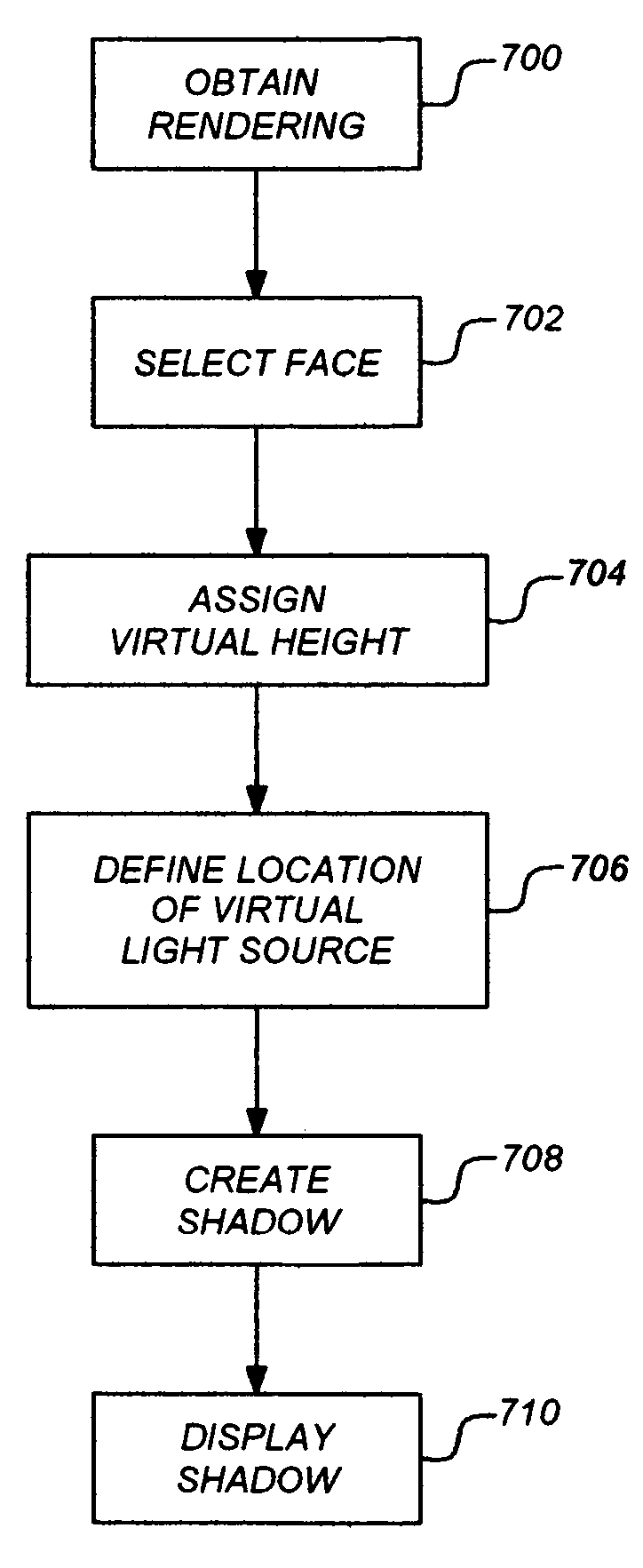
[0025]Embodiments of the invention provide a method, apparatus, system, technique, etc. that casts shadows on a two-dimensional vector-based drawing in an easy intuitive interface.

Hardware and Software Environment

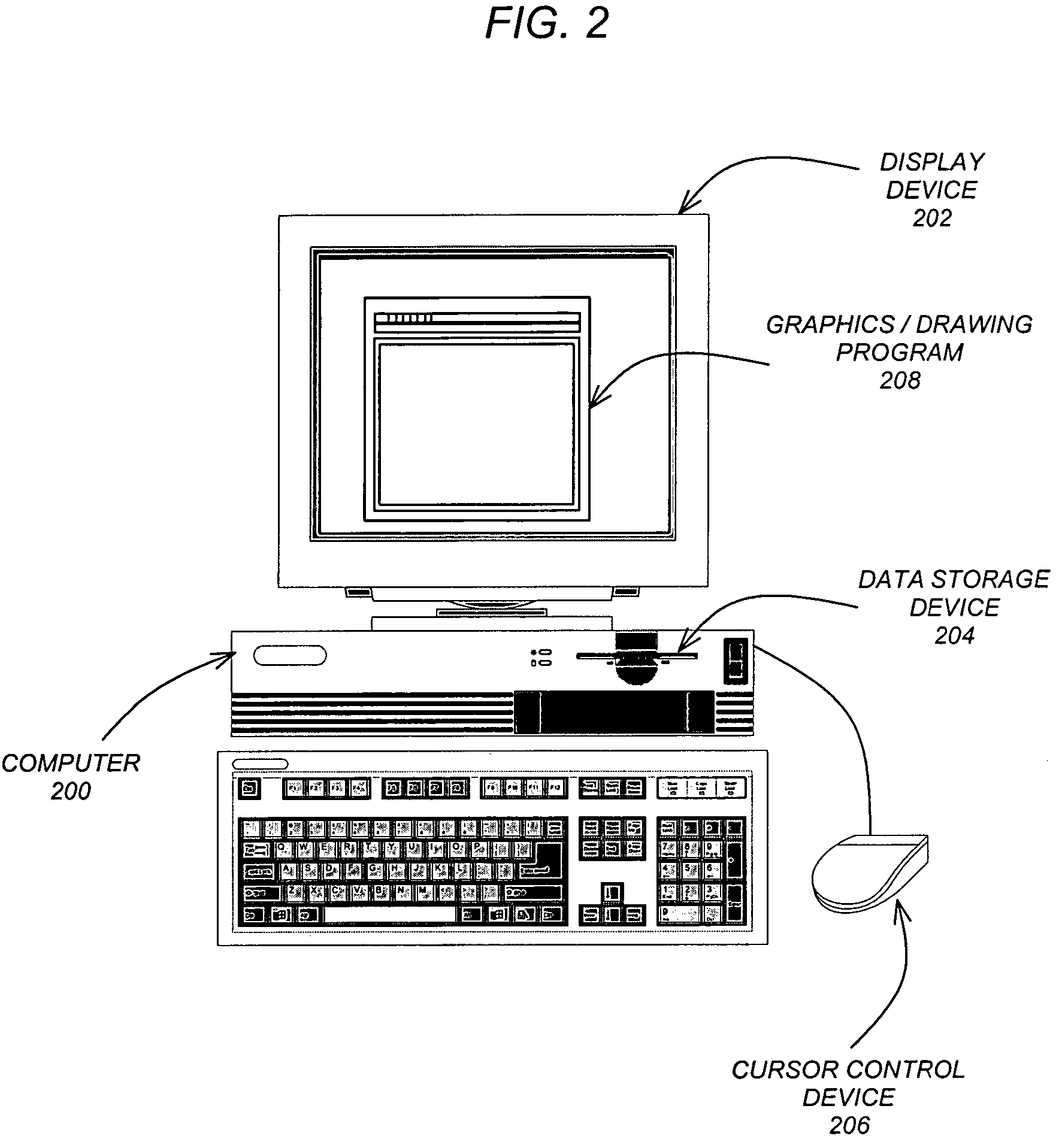
[0026]FIG. 2 is an exemplary hardware and software environment used to implement one or more embodiments of the invention. Embodiments of the invention are typically implemented using a computer 200, which generally includes, inter alia, a display device 202, data storage devices 204, cursor control devices 206, and other devices. Those skilled in the art will recognize that any combination of the above components, or any nu...


PUM


Abstract

A method, apparatus, and article of manufacture are configured to cast a shadow for a two-dimensional vector geometry. A two-dimensional computer-generated rendering comprised of vector geometry is obtained. A face of the vector geometry is then selected and a virtual height is assigned to the face. Once a location of a virtual light source is defined, a shadow for the vector geometry is created and displayed based on the virtual height of the face and the location of the virtual light source.

Description

CROSS-REFERENCE TO RELATED APPLICATIONS[0001]This application is related to the following co-pending and commonly-assigned patent application, which application is incorporated by reference herein:[0002]U.S. patent application Ser. No. 11 / 268,797, entitled “AUTOMATIC ELEMENT SUBSTITUTION IN VECTOR-BASED ILLUSTRATIONS”, by Mason J. Foster, filed on Nov. 8, 2005;[0003]U.S. patent application Ser. No. 11 / 268,796, entitled “DRAWING STYLE DOMAINS”, by Mason J. Foster, Jose Madeira de Freitas Garcia, and Joseph Cleveland Ard, filed on Nov. 8, 2005; and[0004]U.S. patent application Ser. No. 11 / 286,535, entitled “STROKED FILL”, by Nikolai Sander and Mason J. Foster, filed on the same date herewith.BACKGROUND OF THE INVENTION[0005]1. Field of the Invention.[0006]The present invention relates generally to architectural renderings, and in particular, to a method, apparatus, and article of manufacture for displaying / casting a shadow on objects in a two-dimensional architectural rendering.[0007]...

Claims


Application Information

Patent Timeline
Patent Type & Authority Patents(United States)
IPC IPC(8): G06T11/00
CPCG06T15/60
Inventor FOSTER, MASON J.
Owner AUTODESK INC
Why Eureka
Try Eureka