Optical measurement apparatus and method

a measurement apparatus and optical technology, applied in the direction of optical radiation measurement, instruments, spectrometry/spectrophotometry/monochromators, etc., can solve the problems of slow measurement speed, preventing widespread industrial application, and affecting the measurement accuracy

Inactive Publication Date: 2009-11-10
KLA CORP
View PDF4 Cites 14 Cited by
  • Summary
  • Abstract
  • Description
  • Claims
  • Application Information

AI Technical Summary

Problems solved by technology

The measurement of the modulated reflectance (ΔR) signal has some difficulties.
Speed of the measurement is a problem, and has precluded its widespread industrial application in high-speed production line inspection of semiconductor wafers.
This method suffers from a number of difficulties and impracticalities, chief of which is the engineering difficulty and cost of producing a large number of optical pump and probe beams, with sufficient uniformity of illumination, at multiple sites on a sample wafer.

Method used


Image

  • Optical measurement apparatus and method
  • Optical measurement apparatus and method
  • Optical measurement apparatus and method

Examples


example

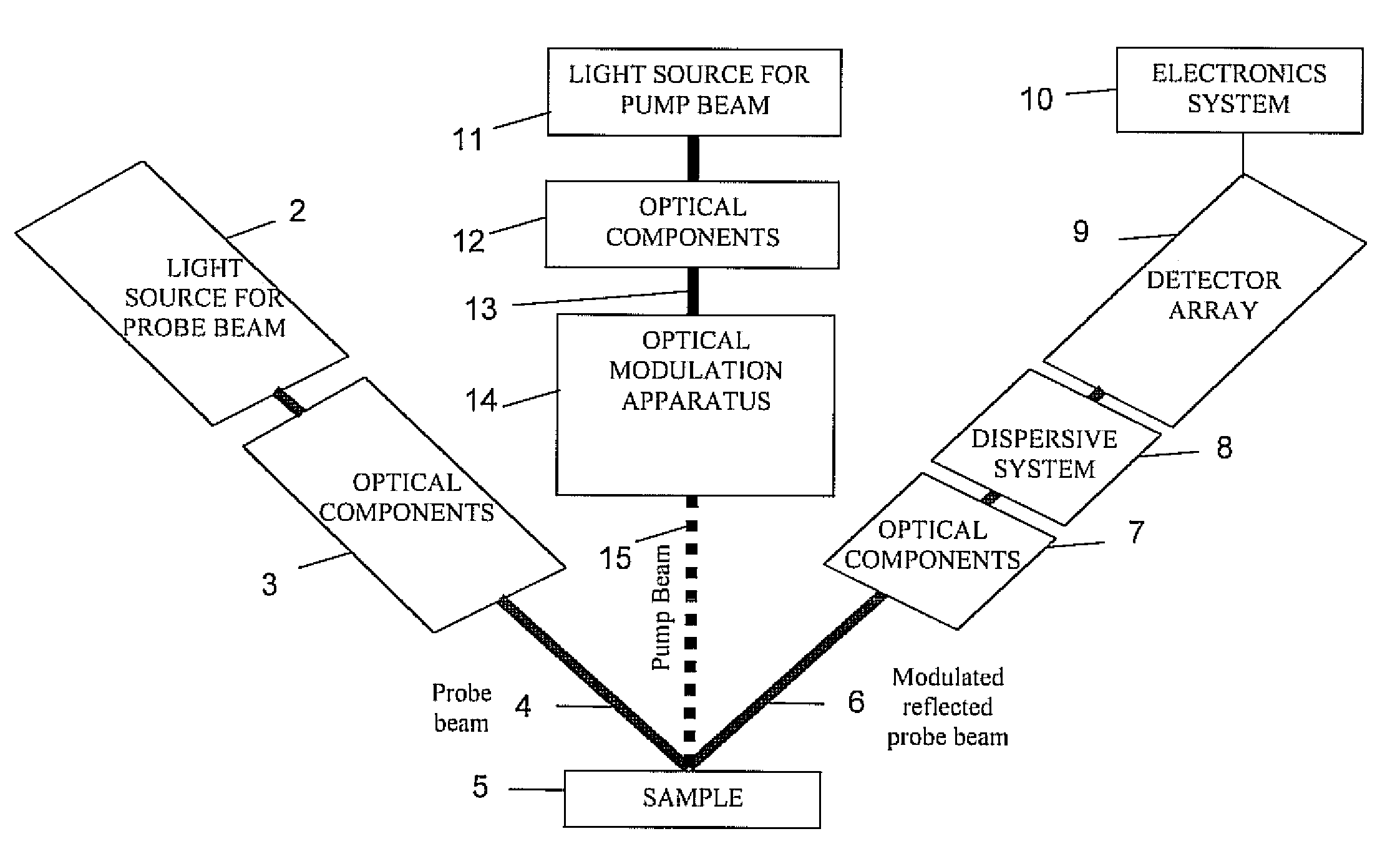
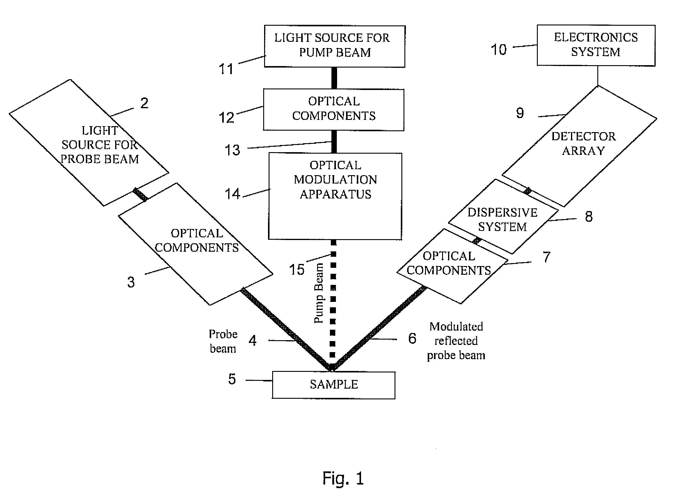
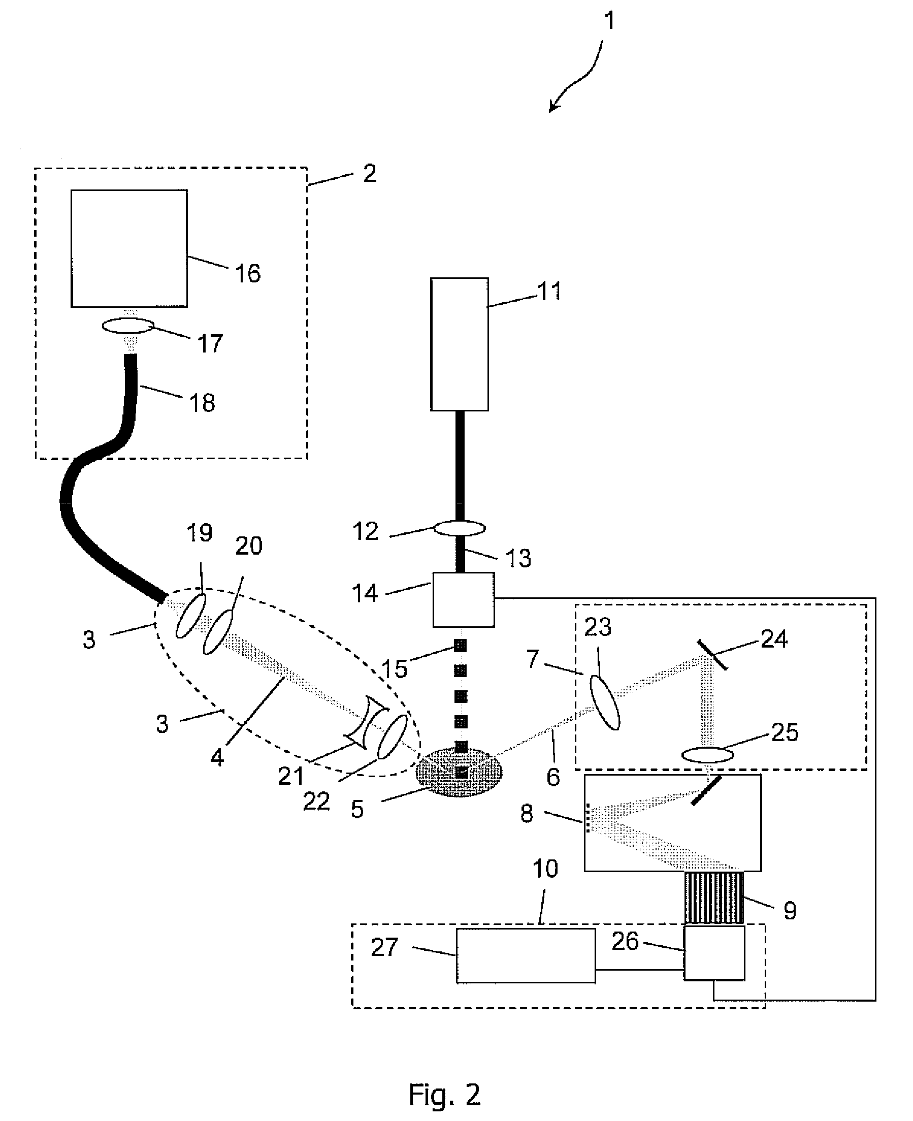
[0200]The following examples are not intended to limit the scope of the invention. In one specific example of the invention, a 300 W Oriel 6258 Ozone-Free Xenon arc lamp was used with reflecting and light collecting to produce a blue and near ultraviolet probe light beam, which was collimated and reflected from a silicon wafer and coupled to an Andor Shamrock SR303i Imaging Spectrograph, fitted with a grating with 600 lines per mm and blazed at 300 nm. To the exit port of the spectrograph was mounted a Hamamatsu S3921-512Q photodetector array. A Coherent 315M 150 mW diode-pumped solid state laser was amplitude modulated at a chopping frequency of 139 Hz using an Ametek optical chopper, and shone over the area of incidence of the probe light beam. A driver circuit designed for the S3921-512Q photodetector array was connected behind the array, and a special circuit designed to lengthen the output video-signal-type pulses from the array and driver circuit, was electrically connected to...

example application

[0204]In one specific example of the invention, the photoreflectance spectrum of a strained silicon layer grown pseudomorphically on a silicon-germanium alloy of Ge alloy mole fraction 20.4%, is measured over the spectral range 2.8 eV to 3.6 eV at intervals of 0.002 eV. The spectrum is fitted to a summation of two low field photoreflectance lineshapes of the form of expression 1 above, and found to have an E1+ transition energy of 3.287 eV, shifted 105 meV from the E1 transition energy of 3.392 eV of unstrained bulk silicon on the substrate of the same wafer. The shifts ΔE in each branch of the split E1 transition energy and their relationship to the in-plane and out-of-plane strain tensor elements ∈⊥ and ∈∥ may be written in the form 3:

ΔE=−3.267(∈⊥+2∈∥)±1.567(∈⊥−∈∥)  3

where the “±” sign is applied as “+” to obtain the shift in the E1+ branch and as “−” to obtain the shift in the E1− branch, from the E1 transition energy of unstrained silicon. Converted to in-plane strain using the ...


PUM


Abstract

An optical modulation spectroscopy system comprises a probe beam source and components for directing the probe beam at a sample. It also may comprise a modulated pump beam source and components for directing a modulated pump beam at the sample. A dispersive system may disperse the reflected probe beam into constituent wavelengths to provide dispersed beams. A detector array may detect multiple dispersed reflected probe beams and processes a signal corresponding to each. Thus, measurement may be multiplexed for very fast performance.

Description

RELATED APPLICATIONS[0001]This application is a continuation of International Application No. PCT / IE2006 / 000118, filed Oct. 24, 2006, which claims the benefit of Provisional Applications Nos. 60 / 729,233, filed Oct. 24, 2005, and 60 / 749,597, filed Dec. 13, 2005, the disclosures of which are incorporated herein in their entirety.INTRODUCTION[0002]1. Field of the Invention[0003]The invention relates to an optical measurement apparatus and method, particularly using modulation spectroscopy.[0004]2. Prior Art Discussion[0005]Modulation spectroscopy is a class of spectroscopy in which the reflectance or transmission of a sample is altered at some parts of the electromagnetic spectrum by means of an external perturbation. Generally, this perturbation is applied in a periodic manner, such that the reflectance or transmission of the semiconductor at the wavelengths where it changes in response to the external perturbation, periodically alternates between the value in the absence of external ...

Claims


Application Information

Patent Timeline
Patent Type & Authority Patents(United States)
IPC IPC(8): G01J3/26
CPCG01N21/1717G01N2021/1725
Inventor MURTAGH, MARTIN EDWARDKELLY, PATRICK VINCENTSOMEKH, MICHAEL GEOFFREYPITTER, MARK CHARLESSHARPLES, STEPHEN DAVID
Owner KLA CORP
Why Eureka
Try Eureka