Flexible hydraulic muscle

a hydraulic muscle and flexible technology, applied in the direction of flexible wall reciprocating engines, positive displacement engines, belt pistons, etc., can solve the problems of limited force, large system to provide large forces, limited force, etc., and achieve the effect of constant retracting for

Inactive Publication Date: 2009-11-17
RAGNER GARY DEAN
View PDF7 Cites 58 Cited by
  • Summary
  • Abstract
  • Description
  • Claims
  • Application Information

AI Technical Summary

Problems solved by technology

To provide the reverse, systems can use negative pressure to contract the muscle, however these are limited to one atmosphere of force (14.7 per square inch).
Bellow systems for use with actuating levers sometimes use this negative vacuum pressure to provide a retracting force, but such force is limited and requires a large system to provide large forces.
Bellows may also work with pressurized air to providing a retracting force, but requires a cylinder housing and piston which does not allow the bellow to be flexible or light-weight.
No known flexible bellow system was found that provides its strongest contracting force while hydraulic fluid pressure is released.
Also, no known hydraulic muscle was found which uses a liquid hydraulic fluid to provide a contracting force during pressure release.
For the Disclosed hydraulic muscle it is actually a disadvantage to transport fluid from one side to the other since this would require an additional fluid return line that is not needed.
However, the flexible nature of the hydraulic muscle (without support guides) prevents it from generating significant extending force.
When hydraulic fluid is released, this tension biasing causes a strong contracting force within the muscle.
Without such side-force support, the muscle can simply flex out of alignment when placed in compression, greatly reducing the extending force possible.

Method used


Image

  • Flexible hydraulic muscle
  • Flexible hydraulic muscle
  • Flexible hydraulic muscle

Examples


Embodiment Construction

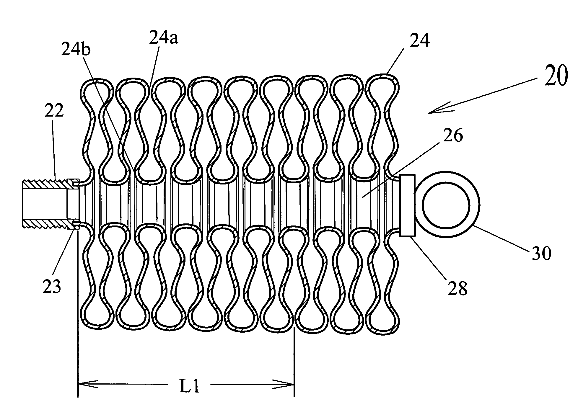
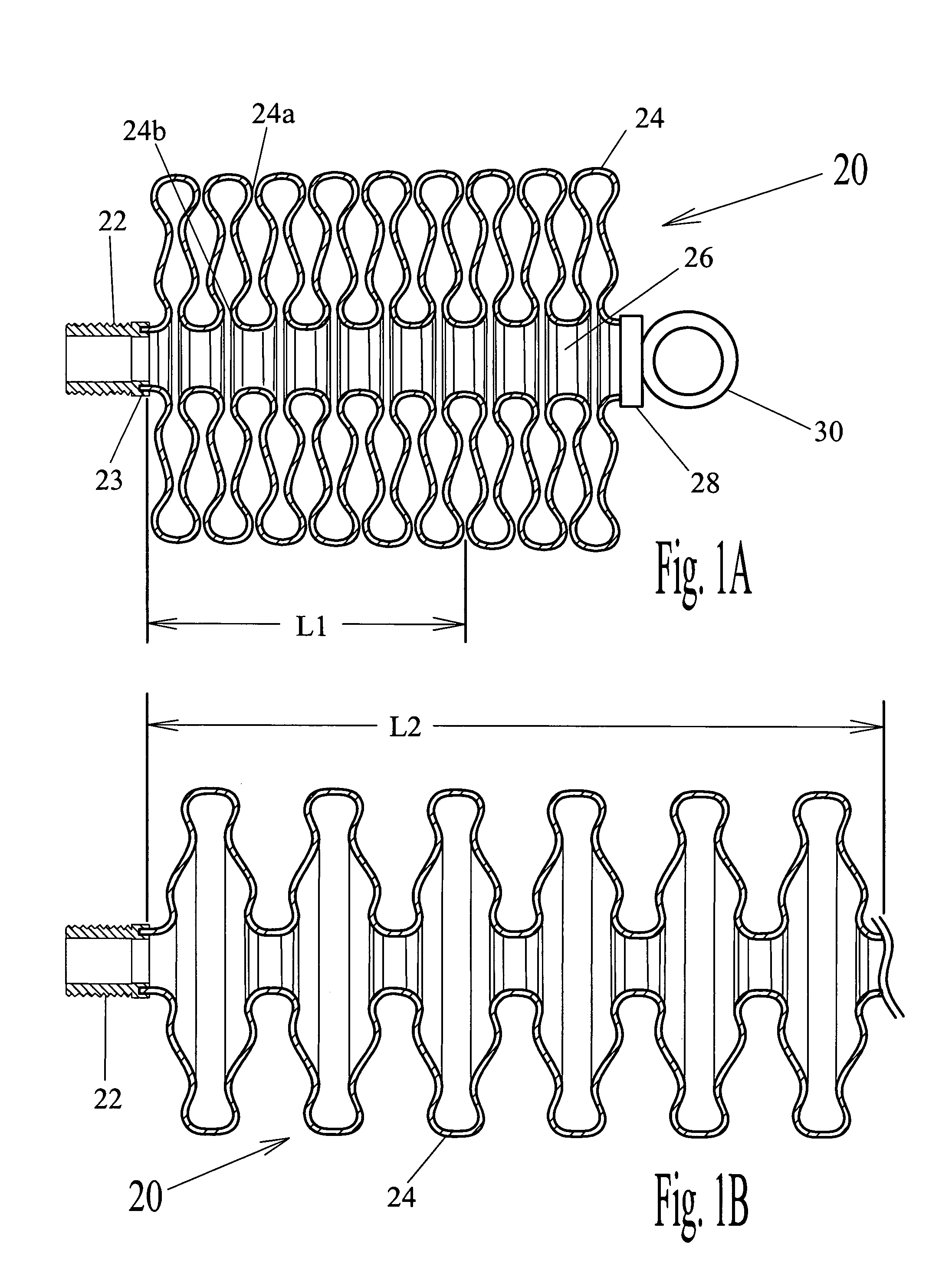
[0039]In FIGS. 1A and 1B we see a flexible hydraulic muscle 20 comprising a fluid port 22, bellow 24, end seal 28 and attachment ring 30. As with the other hydraulic muscles disclosed in this patent, bellow 24 has a generally cylindrical shape, however, other cross-section shapes can be used besides round in the examples except FIG. 4 which requires a substantially round cross-section for support cords 86 to provide proper radial support. Fluid port 22 is designed to provide an anchor point for the muscle, while at the same time, providing a means to introduce and remove hydraulic fluid from bellow 24. Port 22 is shown here with a threaded connector, but other types of connectors can be used. End seal 28 and attachment ring 30 provide the second connecting point for the muscle. These two anchor points on each end of bellow 24 provide connection points to communicate contracting force from bellow 24 into useful work. End seal 28 is securely attached or bonded to the end of bellow 24 ...


PUM


Abstract

A flexible hydraulic muscle (20) comprising a fluid port (22), bellow (24), end seal (28) and attachment ring (30). Bellow (24) also defines a retracting spring bias for generating contracting forces within muscle (20). Fluid port (22) is designed to provide an anchor point for the muscle, while at the same time, providing a means to introduce and remove hydraulic fluid from bellow (24). End seal (28) and attachment ring (30) provide the second connecting point for the muscle. These two anchor points on each end of bellow (24) provide connection points to communicate contracting force from bellow (24) into useful work. End seal (28) is securely attached or bonded to the end of bellow (24) to provide a fluid tight seal, and designed to resist longitudinal forces on the connection.

Description

CROSS-REFERENCE TO RELATED APPLICATIONS[0001]This utility application claims priority from U.S. Provisional application Ser. No. 60 / 480,727, filed on Jun. 23, 2003, titled: “Flexible Hydraulic Muscle”.BACKGROUND[0002]1. Field of Invention[0003]The field of this invention relates to devices that produce useful work from hydraulic pressure, and more specifically devices that do useful work while hydraulic pressure is removed.[0004]2. Description of Prior Art[0005]The disclosed flexible hydraulic muscle is designed to extend while being pressurized with a hydraulic fluid and contract strongly when pressure is released. This is the exact reverse of known prior art, where flexible hydraulic muscles are designed to retract when hydraulic pressure is applied, and extend when pressure is released. To provide the reverse, systems can use negative pressure to contract the muscle, however these are limited to one atmosphere of force (14.7 per square inch). Bellow systems for use with actuating...

Claims


Application Information

Patent Timeline
Patent Type & Authority Patents(United States)
IPC IPC(8): F16J3/04
CPCF16J3/06F15B15/103
Inventor RAGNER, GARY DEAN
Owner RAGNER GARY DEAN
Why Eureka
Try Eureka